Special tool
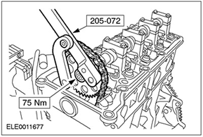
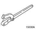 | Universal wrench for holding flanges 205-072 (15-030A) |
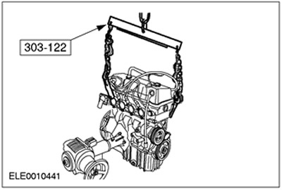
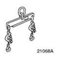 | Engine lift bracket 303-122 (21-068A) |
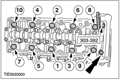
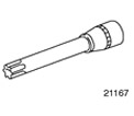 | Socket wrench for cylinder head bolts 303-392 (21-167) |
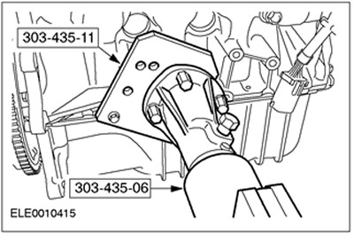
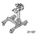 | Stand 303-435 (21-187) |
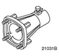 | Support bracket for 303-435 303-435-06 (21-031V) |
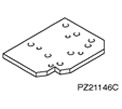 | Base plate for 303-435-06 303-435-11 (21-146C) |
General equipment:
- Piston ring compressor
- steel ruler
- Fixing clamps
| Name | Specification |
| Engine oil | WSS-M2C912-A1 |
| sealant | WSEM-4G323-A |
| sealant | WSK-M2G349-A4 |
1. Install the crankshaft main bearing shells.
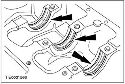
2.
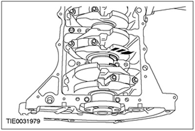
NOTE: Bearing caps are numbered starting at the front of the engine, which is also pointed towards by the arrows.
Install the crankshaft.
- Coat the main journals and bearing shells with clean engine oil.
- Make sure piston #1 is at top dead center (w.m.t.).
3.
NOTE: The grooves in the crankshaft thrust washers must face outwards.
Install the crankshaft thrust washers.
4.
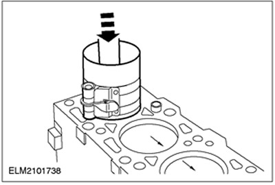
NOTE: Connecting rod numbering starts at the front of the engine. The arrow on the piston head points towards the front of the engine.
Using an appropriate piston ring compressor, install the pistons.
- Coat pistons and cylinder liners with clean engine oil.
- Distribute the piston ring joints evenly around the circumference. This also applies to the elements of the oil scraper ring.
- Using a hammer handle, insert pistons #1 and #4 into the cylinders. The crankpin must be at bottom dead center (n.m.t.).
- Make sure the bearing shells are clean and dry and install them in the appropriate connecting rods and bearing caps.
- Rotate the crankshaft 180 degrees and install pistons #2 and #3.
5.
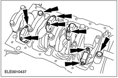
CAUTION: Install new connecting rod bolts.
NOTE: Connecting rods and connecting rod bearing caps are the same numbered.
Install bearing caps.
- Coat the bearing shells and journals with clean engine oil.
- Tighten the bearing cap bolts in two steps.
- Stage 1: 4 Nm
- Stage 2: 90 degrees
6. Install the oil sump baffle.
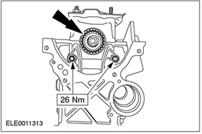
7. Install the timing chain guide, timing chain tensioner arm and crankshaft sprocket.
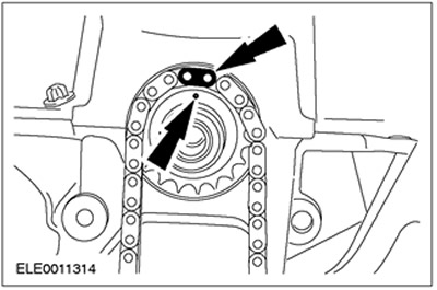
8.
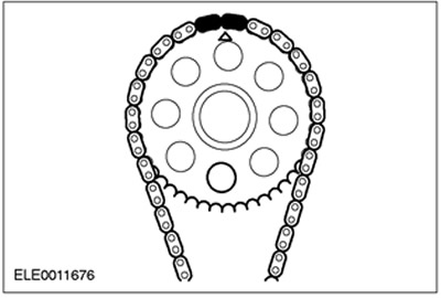
NOTE: The mark on the crankshaft sprocket and the single color-coded timing chain link must be opposite each other.
Install the timing chain.
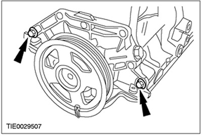
9.
CAUTION: Install the oil pump only with the crankshaft pulley.
CAUTION: When installing a new oil pump, do not remove the crankshaft pulley or clamp before installation.
NOTE: Install a new oil pump gasket.
NOTE: New oil pump comes complete with crankshaft front oil seal and crankshaft pulley.
NOTE: Do not tighten the oil pump mounting bolts at this stage.
Install the oil pump assembly.
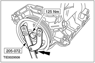
10. Using the special tool, tighten the crankshaft pulley bolt. Remove the assembly clamp.
11.
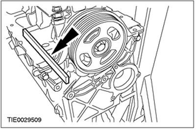
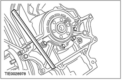
NOTE: The oil pump sealing flange must be within±0.20mm of the bottom sealing flanges of the cylinder block.
Using a suitable ruler, align the position of the sealing flanges of the oil pump and cylinder block.
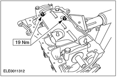
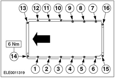
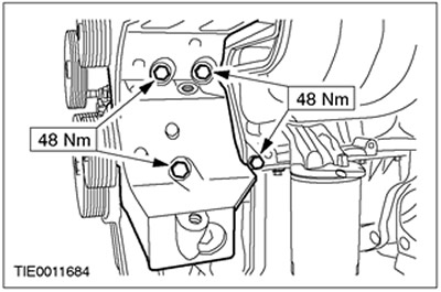
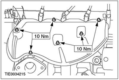
12.
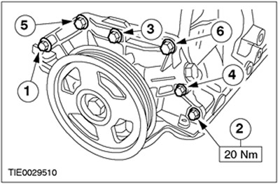
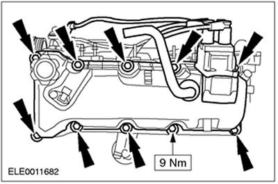
NOTE: Install new sealed bolts in positions 1 and 3.
Tighten the oil pump mounting bolts. Tighten the bolts in the sequence shown.
13.
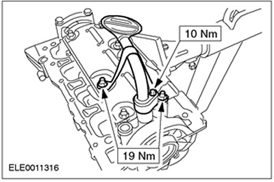
NOTE: Make sure the o-ring is installed correctly.
Install the oil pickup tube.
14.
CAUTION: Do not remove the mounting sleeve before installation.
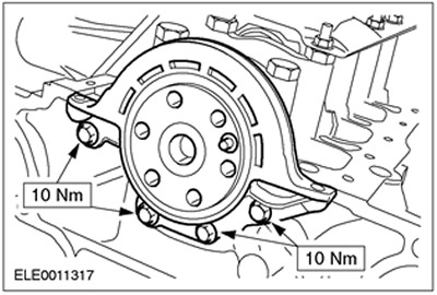
NOTE: Install a new crankshaft rear oil seal retainer.
NOTE: A new rear oil seal carrier is shipped assembled on a locating sleeve.
NOTE: Do not touch the dust collecting tab and the sealing tab.
NOTE: The sealing lug must not be covered with oil.
NOTE: Make sure the dowel pins are installed correctly.
Install the crankshaft rear seal retainer.
15.
CAUTION: Install the oil pan gasket within five minutes of applying the sealant.
Apply sealant to the cylinder block joints.
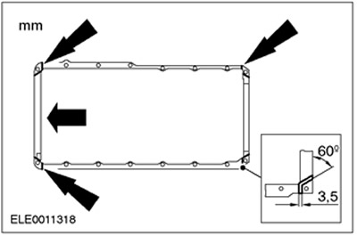
16.
NOTE: Do not fully tighten the oil pan bolts at this stage.
Using a suitable ruler, align the position of the oil sump with respect to the cylinder block.
- Maximum "retreat" oil sump: 0.25 mm.
- Maximum protrusion of the oil sump: 0.10 mm.
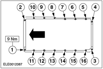
17. Tighten the oil sump bolts in sequence (stage 1).
18. Tighten the oil sump bolts in sequence (stage 2).
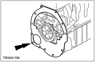
19. Install adapter plate.
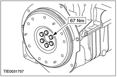
20. Install the flywheel.
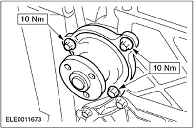
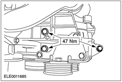
21. Install the water pump.
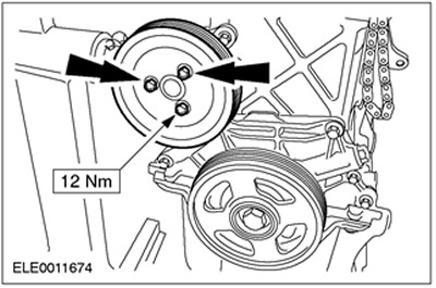
22. Install the water pump pulley.
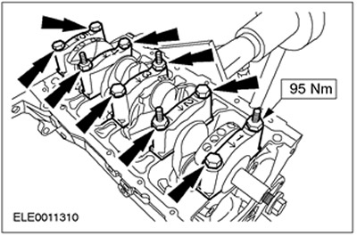
23.
NOTE: Install a new cylinder head gasket.
NOTE: Install new cylinder head bolts.
NOTE: Pass the timing chain through the cylinder head and tie it to the cylinder head.
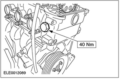
Using the special tool, install the cylinder head.
- Tighten the cylinder head bolts in the sequence shown in four steps.
- Stage 1: Tighten bolts 1 to 10 to 40 Nm.
- Stage 2: Tighten the front two bolts (M8) force 15 Nm.
- Stage 3: Tighten the front two bolts (M8) at 45 degrees.
- Step 4: Turn bolts 1 to 10 120 degrees.
24.
NOTE: The timing mark on the camshaft sprocket must be in position "12 hours".
NOTE: The timing mark on the camshaft sprocket and the marked links on the timing chain must be opposite each other.
Slide the timing chain onto the camshaft sprocket. The timing mark of the camshaft sprocket must be in position "12 hours" when cylinder No. 1 is in the v.m.t.
25. Using the special tool, install the camshaft sprocket.
26. Install the dipstick and oil level indicator tube. Apply sealant to the base end of the oil dipstick tube.
27. Install the hydraulic timing chain tensioner.
28.
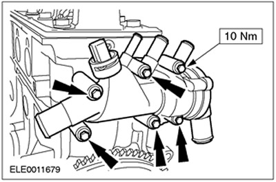
NOTE: If necessary, install a new coolant circulation control unit gasket.
Install the coolant circulation control unit.
29.
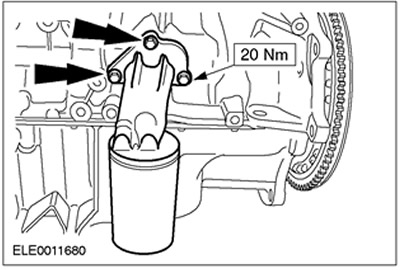
NOTE: Install a new oil filter adapter gasket.
Install the oil filter adapter.
30. Install a new oil filter.
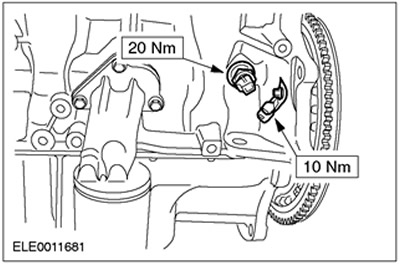
31. Install the crankshaft position sensor (CKP) and oil pressure switch.
32.
NOTE: Install a new cylinder head cover gasket if necessary.
Install the cylinder head cover.
33.
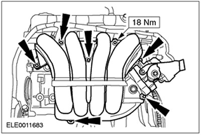
NOTE: Install a new intake manifold gasket if necessary.
Install the intake manifold.
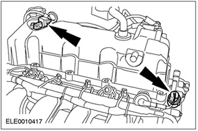
34. Connect the plug connectors of the camshaft position sensor (CMP) and engine coolant temperature sensor (ECT).
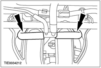
35. Connect the positive crankcase ventilation hose (PCV) to the intake manifold.
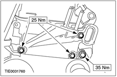
36. Establish an arm of fastening of the generator.
37. Install the generator.
38. Install the front engine mount bracket.
39. Install the special tool.
40. Remove special tools.
41.
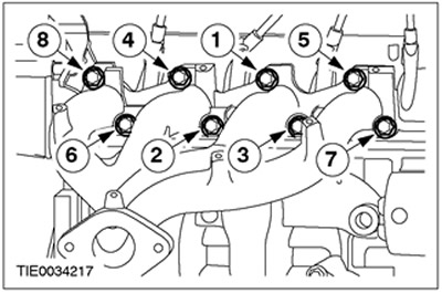
NOTE: Install a new exhaust manifold gasket.
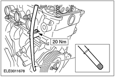
Install the exhaust manifold.
- Tighten the nuts working in the sequence shown in two steps.
- Stage 1: 15 Nm
- Stage 2: 20 Nm
42. Install the exhaust manifold heat shield.
Visitor comments