Special tool
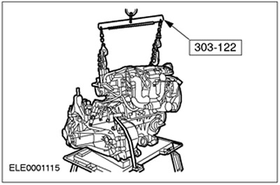
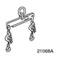 | Engine lift bracket 303-122 (21-068A) |
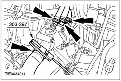
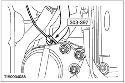
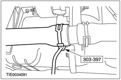
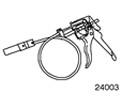 | Clamp remover/installer 303-397 (24-003) |
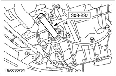
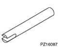 | Axle puller 308-237 (16-087) |
General equipment:
- Crafting table
- Fixing clamps
- Engine Crane
All cars
WARNING: Do not smoke or walk with a lit cigarette or any type of open flame while working on or near fuel related items. In such situations, there are always highly flammable mixtures that can ignite. Failure to follow these instructions may result in injury.
1. Relieve fuel system pressure. Refer to Section 310-00 for more information.
2. Disconnect the battery. Refer to Section 414-01 for more information.
3. Remove the air filter. See Section 303-12 for more information.
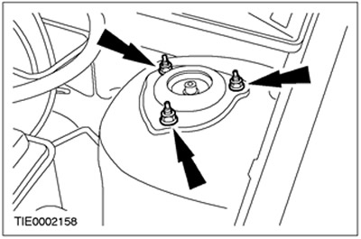
4. Loosen the nut of the top support of the strut assembly with the spring five turns (at both sides).
5. Disconnect the fuel supply and return quick couplers. Refer to Section 310-00 for more information.
6. Drain the coolant from the cooling system. Refer to Section 303-03 for more information.
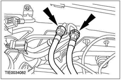
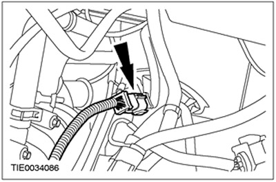
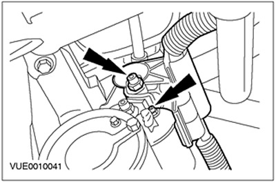
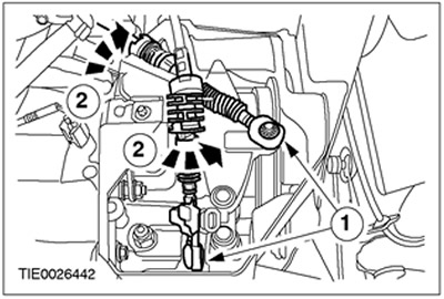
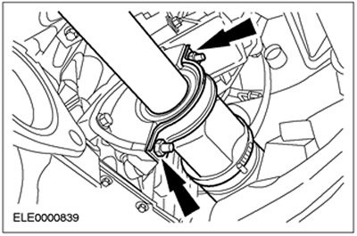
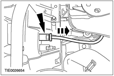
7. Using the special tool, disconnect the coolant hoses from the coolant circulation control unit.
8. Disconnect the vacuum line of the brake booster from the intake manifold.
9. Disconnect the plug connector of the electronic ignition unit (EI).
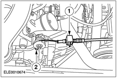
10. Disconnect the accelerator cable from the throttle body and position it to the side.
- 1.Disconnect the accelerator cable outer sheath from the throttle body bracket.
- 2.Disconnect the inner throttle cable from the throttle body lever.
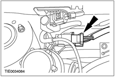
11. Disconnect the plug connector of the engine wiring harness.
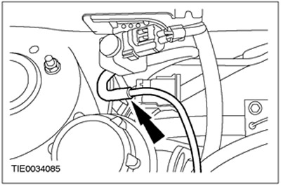
12. Disconnect the vacuum hose from the carbon filter cleaning valve of the fuel vapor control system (EVAP).
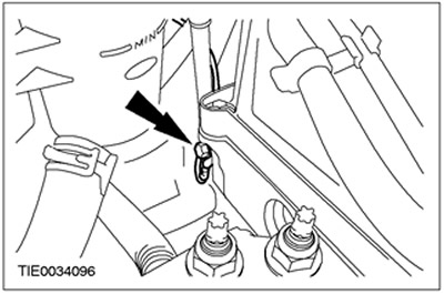
13. Disconnect the ground cable from the cylinder head.
14. Disconnect the plug connector of the transmission wiring harness in the block with the drive axle.
15. Disconnect the power steering pressure switch connector (PSP).
16. Disconnect the power steering line bracket and ground cable from the transaxle.
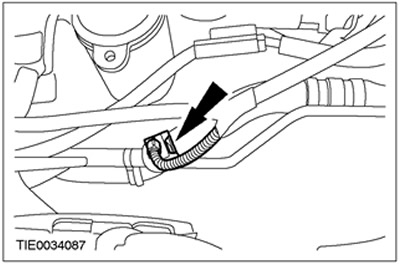
17. Using the special tool, disconnect the coolant hose.
18. Remove accessory drive belt Refer to Section 303-05 for more information.
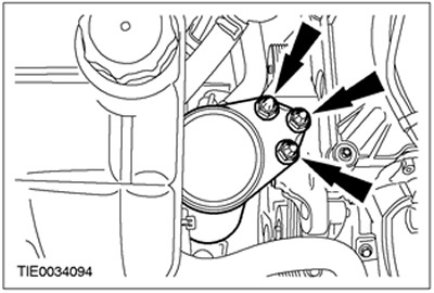
19. Disconnect the power steering pump from the appropriate bracket and secure it to the side.
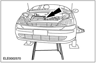
20. Raise and support the vehicle. See Section 100-02 for more information.
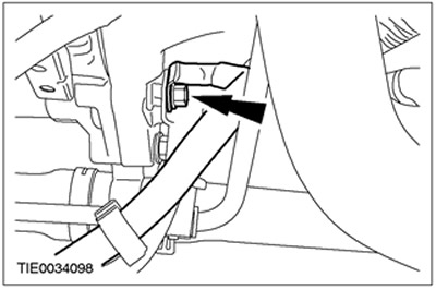
21. Disconnect starter electrical connections.
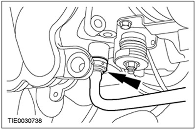
22. Using the special tool, disconnect the coolant hose.
23. Remove the shift cable cover.
24. Disconnect the shift cables from the gearbox in the block with the drive axle.
- 1. Disconnect the shift cables and gear select cable from the gear select levers.
- 2.Turn the support sleeve clockwise and disconnect the cables from the bracket.
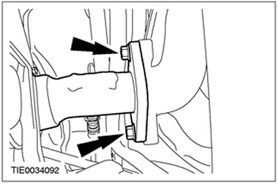
25. Disconnect the flexible exhaust pipe from the exhaust manifold. Discard the gasket as it is no longer needed.
Vehicles with air conditioning
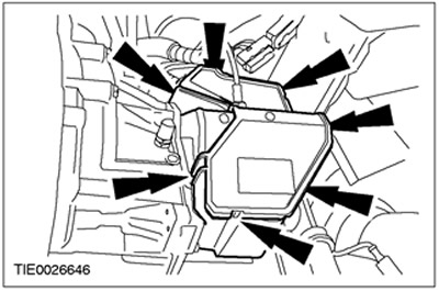
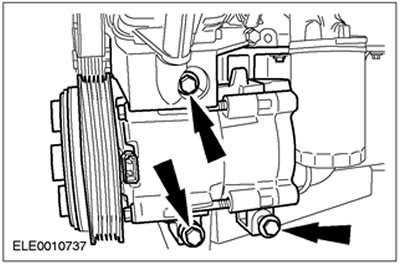
26. Detach the A/C compressor from the appropriate bracket and secure it to the side (shown with engine removed for clarity).
All cars
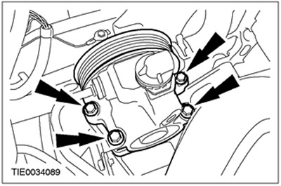
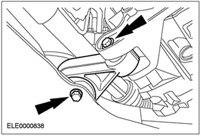
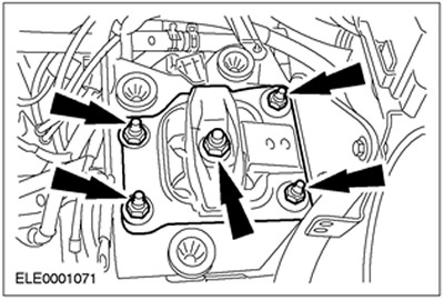
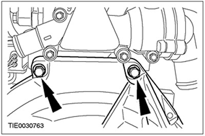
27. Remove the engine mount.
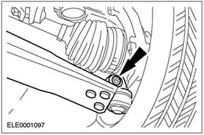
28. Disconnect the lower arm from the steering knuckle (at both sides).
29.
CAUTION: Secure the axle shaft to prevent damage to the CV joints. The inner hinge should not be deflected more than 18 degrees. The outer hinge should not be tilted more than 45 degrees.
CAUTION: Be careful not to damage the axle shaft seal.
NOTE: Shut off the transaxle to prevent oil leakage and dirt ingress.
Disconnect the axle shaft with the intermediate shaft from the gearbox in the block with the driving axle and secure it to the side.
- Remove the intermediate shaft bearing cap.
- Discard the bearing cap and locknuts as they are no longer needed.
- Allow the oil to drain into a suitable container.
30.
CAUTION: Secure the axle shaft to prevent damage to the CV joints. The inner hinge should not be deflected more than 18 degrees. The outer hinge should not be tilted more than 45 degrees.
CAUTION: Be careful not to damage the axle shaft seal.
NOTE: Shut off the transaxle to prevent oil leakage and dirt ingress.
Using the special tool, disengage the left axle shaft from the transaxle and secure it out of the way.
- Allow the oil to drain into a suitable container.
- Discard the snap ring as it is no longer needed.
31. Install a workbench under the engine assembly with the gearbox in the block with the drive axle.
32.
WARNING: Support the engine/gearbox assembly in the transaxle block using wooden blocks and secure it using the appropriate clamps. Failure to follow this instruction may result in injury.
Carefully lower the vehicle so that the engine/gearbox assembly sits on the workbench.
33.
WARNING: If brake fluid comes into contact with the paintwork, the affected area must be washed immediately with cold water.
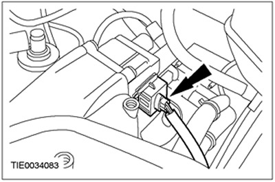
Disconnect the clutch slave cylinder supply line. Remove the spring clip.
34. Remove the rear engine mount nuts. Discard the nuts as they are no longer needed.
35. Remove the nuts securing the front engine mount. Discard the nuts as they are no longer needed.
36. Raise the car and remove the engine assembly with the gearbox in the block with the drive axle.
37. Using the special tool, connect the engine/gearbox assembly to the engine hoist.
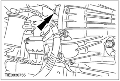
38. Turn out the left bolt of fastening of a transmission in the block with the leading bridge.
39. Remove the starter.
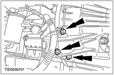
40. Turn out the right bolts of fastening of a transmission in the block with the leading bridge.
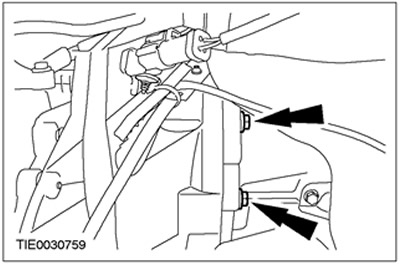
41. Turn out the bottom bolts of fastening of a transmission in the block with the leading bridge.
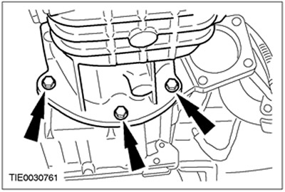
42. Turn out the top bolts of fastening of a transmission in the block with the leading bridge.
43. Remove the gearbox in the block with the drive axle.
Visitor comments