Special tool
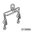 | Engine lift bracket 303-122 (21-068A) |
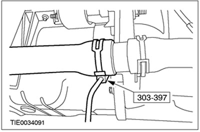
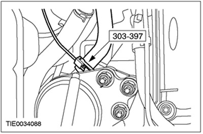
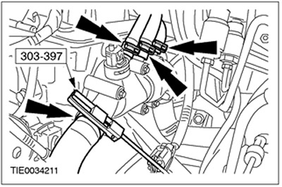
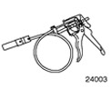 | Clamp remover/installer 303-397 (24-003) |
General equipment:
- Fixing clamps
- Crafting table
- Engine Crane
- wooden block
All cars
WARNING: Do not smoke or walk with a lit cigarette or any type of open flame while working on or near fuel related items. In such situations, there are always highly flammable mixtures that can ignite. Failure to follow these instructions may result in injury.
1. Install the gearbox in the block with the drive axle.
2.
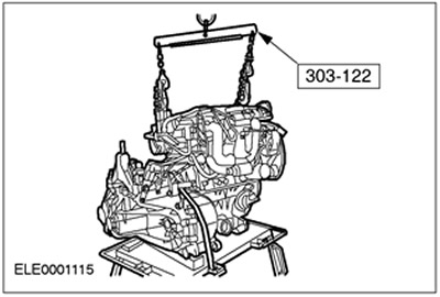
WARNING: Support the engine/gearbox assembly in the transaxle block using wooden blocks and secure it using the appropriate clamps.
Using the special tool and a crane to lift the engine, place the engine and transaxle assembly on a workbench.
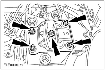
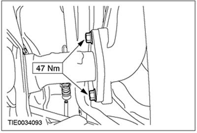
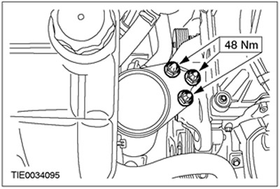
3. Establish the top bolts of fastening of a transmission in the block with the leading bridge.
4. Establish the bottom bolts of fastening of a transmission in the block with the leading bridge.
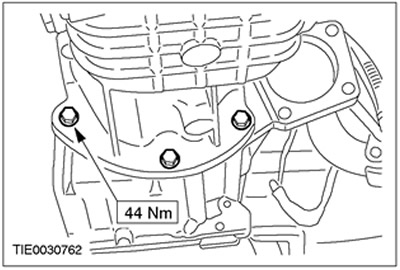
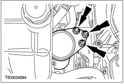
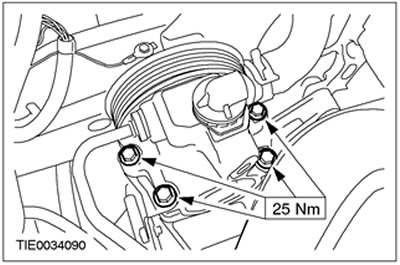
5. Establish the right bolts of fastening of a transmission in the block with the leading bridge.
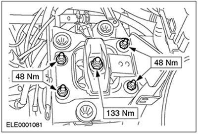
6. Install starter.
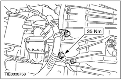
7. Connect the starter connectors.
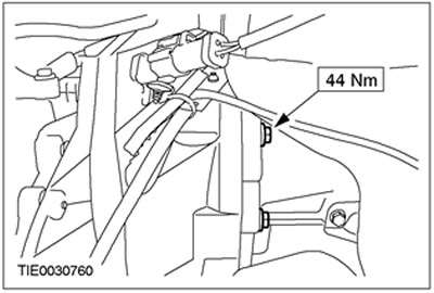
8. Establish the left bolt of fastening of a transmission in the block with the leading bridge.
9. Raise and support the vehicle. Refer to Section 100-02 for more information.
10. Position a workbench under the vehicle and carefully lower the vehicle until the engine/transaxle assembly is in the position required to install the engine mounts.
11.
NOTE: Install new front engine mount nuts.
NOTE: Do not tighten the front engine mount nuts at this stage.
Install the front engine mount nuts.
12.
NOTE: Install new rear engine mount nuts.
NOTE: Do not tighten rear engine mount nuts at this stage.
Install the rear engine mount.
13.
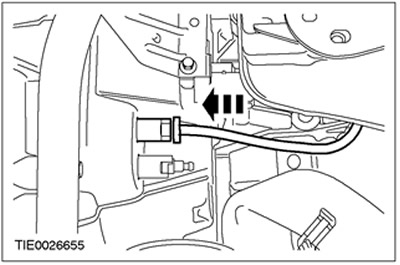
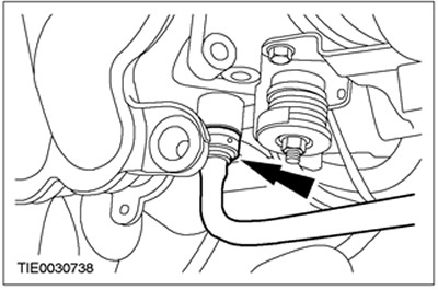
WARNING: If brake fluid comes into contact with the paintwork, the affected area must be washed immediately with cold water.
Connect the supply line to the clutch slave cylinder.
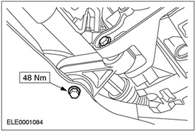
14. Install the engine mount.
15.
CAUTION: Secure the axle shaft to prevent damage to the CV joints. The inner hinge should not be deflected more than 18 degrees. The outer hinge should not be tilted more than 45 degrees.
CAUTION: Be careful not to damage the axle shaft seal.
CAUTION: Make sure the snap ring is installed correctly.
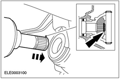
NOTE: Install a new circlip.
Connect the left axle shaft to the gearbox in the block with the drive axle.
16.
CAUTION: Secure the axle shaft to prevent damage to the CV joints. The inner hinge should not be deflected more than 18 degrees. The outer hinge should not be tilted more than 45 degrees.
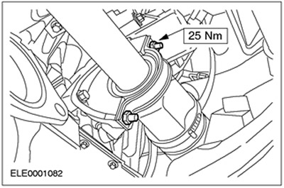
NOTE: Install a new intermediate shaft intermediate bearing cap and locknuts.
Connect the axle shaft together with the intermediate shaft to the gearbox in the block with the drive axle.
17.
CAUTION: To prevent damage to the ball joint, make sure the heat shield is installed.
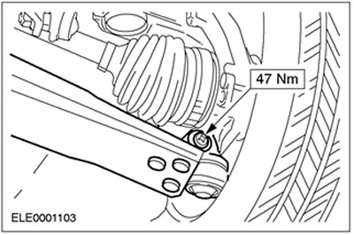
CAUTION: The lower arm pinch bolt must be installed at the rear of the steering knuckle.
Connect the lower arms to the steering knuckles on both sides.
Vehicles with air conditioning
18. Connect the air conditioning compressor (A/C) to the appropriate bracket.
All cars
19. Connect the flexible exhaust pipe to the exhaust manifold.
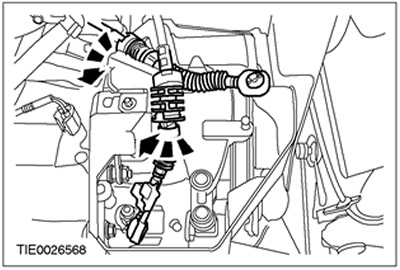
20. Connect the shift cables to the gearbox in the block with the drive axle. Rotate the support bushings counterclockwise and connect the cables to the bracket.
21. Adjust shift cable. Refer to Section 308-00 for more information.
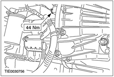
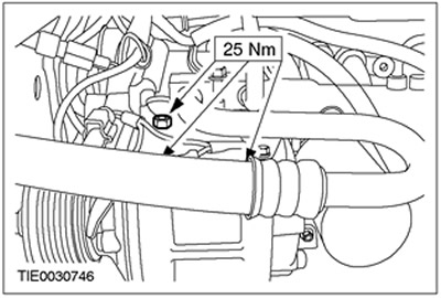
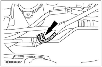
22. Using the special tool, connect the coolant hose.
23. Lower the car.
24. Tighten the front engine mount nuts.
25.
NOTE: Install new rear engine mount nuts.
Tighten the rear engine mount nuts.
26. Attach the power steering pump to the appropriate bracket.
27. Using the special tool, connect the coolant hose.
28. Install the accessory drive belt. Refer to Section 303-05 for more information.
29. Attach the power steering line mounting bracket and ground cable to the transmission in the drive axle assembly.
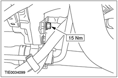
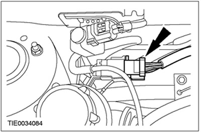
30. Connect the power steering pressure switch connector (PSP).
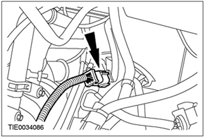
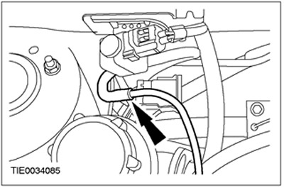
31. Dock the plug connector of the transmission wiring harness in the block with the drive axle.
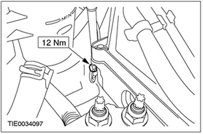
32. Connect the ground cable to the cylinder head.
33. Connect a vacuum hose to the carbon filter cleaning valve of the fuel vapor control system (EVAP).
34. Dock the plug connector of the engine wiring harness.
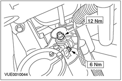
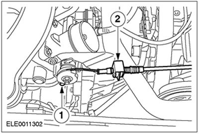
35. Connect the accelerator cable to the throttle body.
- 1. Connect the inner throttle cable to the throttle body lever.
- 2. Connect the accelerator cable outer sheath to the throttle body bracket.
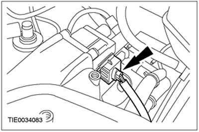
36. Dock the plug connector of the electronic ignition unit (EI).
37. Connect the vacuum line of the brake booster to the intake manifold.
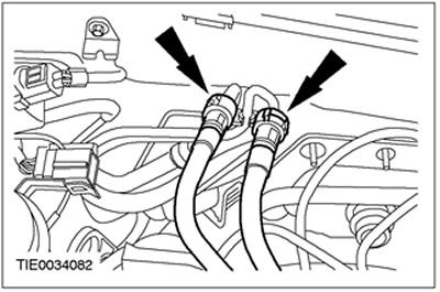
38. Using the special tool, connect the coolant hoses to the coolant circulation control housing.
39. Connect fuel supply and return fuel quick couplings. Refer to Section 310-00 for more information.
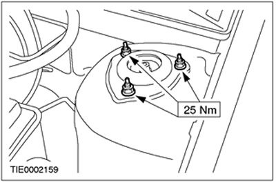
40. Tighten the nuts of the upper support of the suspension strut assembly with the spring (at both sides).
41. Check the transmission fluid level and add manual transmission fluid if necessary. See Section 308-00 for more information.
42. Install the air filter. See Section 303-12 for more information.
43. Connect the battery. See Section 414-01 for more information.
44. Refill the engine cooling system. See Section 303-03 for more information.
45. Remove air from the hydraulic clutch. See Section 308-00 for more information.
Visitor comments