|
STATES |
DETAILS/RESULTS/ACTIONS |
|
A1: CHECK FUSE 8 (30 A) |
|
|
1 Disconnect Fuse 8 (30A). |
|
|
2 CHECK. |
|
|
3 Check fuse 8 (30 A). |
|
|
• Is the fuse good? |
|
|
→ Yes |
|
|
Go to A2 |
|
|
→ No |
|
|
Install new fuse 8 (30 A). Check the correct operation of the system. If the fuse blows again, check circuit 30 (red) for a short circuit "mass". |
|
|
A2: CHECKING THE IGNITION SWITCH CONNECTOR |
|
|
1 Remove the steering column cover and check the ignition switch connector. |
|
|
• Ignition switch connector OK (cleanliness and security)? |
|
|
→ Yes |
|
|
Go to A3 |
|
|
→ No |
|
|
If necessary, clean and secure the ignition switch connector. Check the correct operation of the system. |
|
|
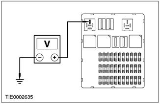
A3: CHECK CIRCUIT 30 (RED) FOR BREAKS. |
|
|
NOTE: Make sure the ground contact is clean before starting the test. |
|
|
1 Connect Fuse 8 (30 A). |
|
|
2 Disconnect the Ignition Switch - C456. |
|
|
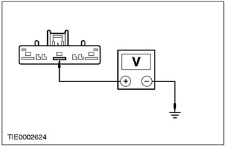
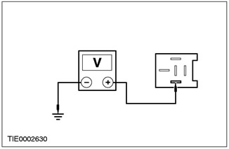
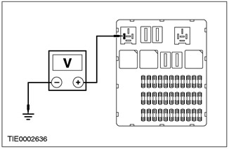
3 Measure the voltage between C456 pin 4 of the ignition switch, circuit 30 (red), And "mass. |
|
• Is the voltage over 10 V? |
|
|
→ Yes |
|
|
Go to A4 |
|
|
→ No |
|
|
Repair electrical circuit 30 (red). Check the correct operation of the system. |
|
|
A4: CHECK IGNITION SWITCH |
|
|
1 Perform ignition switch test. See Section 700-09 for more information "Wiring diagrams", where information about circuits and electrical elements is given. |
|
|
• Is the ignition switch OK? |
|
|
→ Yes |
|
|
Check the validity of the customer's complaint. |
|
|
→ No |
|
|
Install a new ignition switch. For more information, see paragraph "ignition switch" in this section. Check the correct operation of the system. |
|
PINPOINT TEST B: NO POWER IN POSITION "ACC".
|
STATES |
DETAILS/RESULTS/ACTIONS |
|
B1: CHECK FUSE 50 (7.5 A) |
|
|
1 Disconnect Fuse 50 (7.5 A). |
|
|
2 CHECK. |
|
|
3 Check fuse 50 (7.5 A). |
|
|
• Is the fuse good? |
|
|
→ Yes |
|
|
Navigate to B2 |
|
|
→ No |
|
|
Install a new fuse. Check the correct operation of the system. If the fuse blows again, check for a short to "mass" pin 14 of the central timer module or circuits 75 (yellow/green) and 75 (yellow/blue). |
|
|
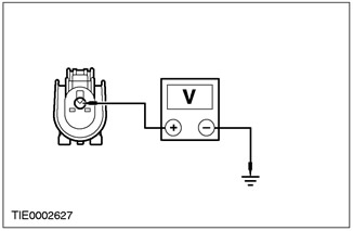
B2: CHECK FOR VOLTAGE AT FUSE 50 (7.5 A) |
|
|
NOTE: Make sure the ground contact is clean before starting the test. |
|
|
1 Enter the ACCESSORY position. |
|
|
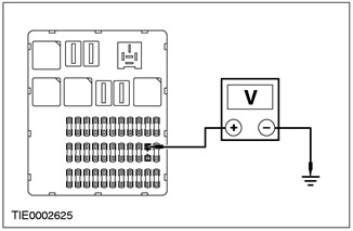
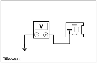
2 Measure the voltage between pin 1 of fuse 50 (7.5 A), chains 75 (yellow), And "weight". |
|
• Is the voltage over 10 V? |
|
|
→ Yes |
|
|
Go to B3 |
|
|
→ No |
|
|
Repair electrical circuit 75 (yellow). Check the correct operation of the system. |
|
|
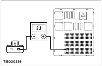
B3: INSPECT CENTRAL JOINT BOX CIRCUIT (CJB) FOR BREAKS. |
|
|
1 Disconnect C13 CJB. |
|
|
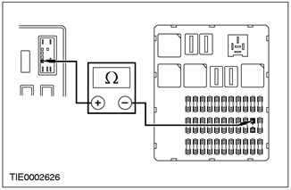
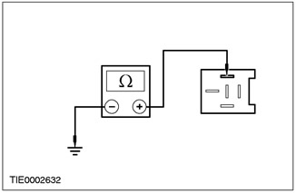
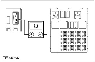
2 Measure the resistance between C13 CJB pin 9 and fuse 50 pin 2 (7.5 A). |
|
• Is the resistance less than 5 ohms? |
|
|
→ Yes |
|
|
Go to B4 |
|
|
→ No |
|
|
Install a new CJB. Check the correct operation of the system. |
|
|
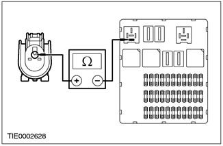
B4: INSPECT ELECTRICAL CIRCUIT 75 (YELLOW) FOR GAPS |
|
|
1 Disconnect the Ignition Switch - C456. |
|
|
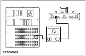
2 Measure the resistance between pin 1 of fuse 50 (7.5 A), electrical circuit 75 (yellow), and pin 6 C456 of the ignition switch, electrical circuit 75 (yellow). |
|
• Is the resistance less than 5 ohms? |
|
|
→ Yes |
|
|
Go to B5 |
|
|
→ No |
|
|
Repair electrical circuit 75 (yellow). Check the correct operation of the system. |
|
|
B5: IGNITION SWITCH TEST |
|
|
1 Perform ignition switch test. See section 700-09 for more information "Wiring diagrams", where information about connections and electrical elements is given. |
|
|
• Check the legitimacy of the customer's complaint. |
|
|
→ Yes |
|
|
Install a new ignition switch. |
|
|
→ No |
|
|
For more information, see paragraph "ignition switch" in this section. Check the correct operation of the system. |
|
PINPOINT TEST C: NO POWER IN POSITION "RUN"
|
STATES |
DETAILS/RESULTS/ACTIONS |
|
C1: CHECK ELECTRICAL CIRCUIT 15 (GREEN/BLUE) and 15 (GREEN/YELLOW) FOR GAPS |
|
|
NOTE: Make sure the ground contact is clean before starting the test. |
|
|
1 Disconnect Ignition Relay - C1001. |
|
|
2 Drive the ON position. |
|
|
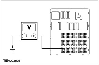
3 Measure the voltage between pin 1 of the C1001 ignition relay, circuits 15 (green/blue) and 15 (green/yellow), And "weight". |
|
• Is the voltage over 10 V? |
|
|
→ Yes |
|
|
Go to C2 |
|
|
→ No |
|
|
Go to C6 |
|
|
C2: CHECK CIRCUIT 30 (RED) FOR GAPS |
|
|
NOTE: Make sure the ground contact is clean before starting the test. |
|
|
1 Enter the OFF position. |
|
|
2 Measure voltage between C1001 ignition relay pin 3, circuit 30 (red), And "weight". |
|
• Is the voltage over 10 V? |
|
|
→ Yes |
|
|
Go to C3 |
|
|
→ No |
|
|
Repair electrical circuit 30 (red). Check the correct operation of the system. |
|
|
C3: INSPECT ELECTRICAL CIRCUIT 91 (BLACK/BLUE) FOR GAPS |
|
|
1 Measure the resistance between pin 2 C1001 ignition relay circuit 91 (black/blue), And "weight". |
|
• Is the resistance less than 5 ohms? |
|
|
→ Yes |
|
|
Go to C4 |
|
|
→ No |
|
|
Repair electrical circuit 91 (black/blue). Check the correct operation of the system. |
|
|
C4: CHECK FUSE F1 (40 A). |
|
|
1 Disconnect Fuse 1 (40A). |
|
|
2 CHECK. |
|
|
3 Check fuse 1 (40 A). |
|
|
• Is the fuse good? |
|
|
→ Yes |
|
|
Go to C5 |
|
|
→ No |
|
|
Install a new fuse. Check the correct operation of the system. If the fuse blows again, check circuit 15 (green/red) for breaks. |
|
|
C5: CHECK CIRCUIT 15 (GREEN/RED) FOR GAPS |
|
|
NOTE: Make sure the ground contact is clean before starting the test. |
|
|
1 Connect Fuse 1 (40 A). |
|
|
2 Connect the Ignition Relay. |
|
|
3 Disconnect Fuse 53 (10 A). |
|
|
4 Drive the ON position. |
|
|
5 Measure the voltage between pin 1 of fuse 53 (10 A), electrical circuit 15 (green/red), And "weight". |
|
• Is the voltage over 10 V? |
|
|
→ Yes |
|
|
Go to C7 |
|
|
→ No |
|
|
Go to C8 |
|
|
C6: CHECK IGNITION SWITCH |
|
|
1 Perform ignition switch test. See section 700-09 for more information "Wiring diagrams", where information about connections and electrical elements is given. |
|
|
• Is the ignition switch OK? |
|
|
→ Yes |
|
|
Repair electrical circuit 15 (blue/light blue) or 15 (green/yellow). |
|
|
→ No |
|
|
Install a new ignition switch. For more information, see paragraph "ignition switch" in this section. Check the correct operation of the system. |
|
|
C7: IGNITION RELAY TEST |
|
|
1 Check the ignition relay. See section 700 - 09 for more information "Wiring diagrams", where information about connections and electrical elements is given. |
|
|
• Relay OK? |
|
|
→ Yes |
|
|
Go to C8 |
|
|
→ No |
|
|
Install a new relay. Check the correct operation of the system. |
|
|
C8: INSPECT CENTER CONNECTION BOX FOR OPEN CIRCUIT. |
|
|
1 Disconnect C18 CJB. |
|
|
2 Measure the resistance between C18 CJB pin 1, circuit 15 (green/red), and pin 1 of fuse 53 (10A), electrical circuit 15 (green/red). |
|
• Is the resistance less than 5 ohms? |
|
|
→ Yes |
|
|
Repair electrical circuit 15 (green/red). Check the correct operation of the system. |
|
|
→ No |
|
|
Install a new CJB. Check the correct operation of the system. |
|
PINPOINT TEST D: NO POWER IN POSITION "START"
|
STATES |
DETAILS/RESULTS/ACTIONS |
|
D1: IN STARTER INTERLOCK RELAY WHEN IGNITION SWITCH IS TURNED TO "START" IS THERE AUDIBLE CLICK? |
|
|
1 Drive the START position. |
|
|
2 Turn the ignition switch to "START". |
|
|
• Does the starter lock relay click? |
|
|
→ Yes |
|
|
Go to D2 |
|
|
→ No |
|
|
Go to D5 |
|
|
D2: CHECK FOR VOLTAGE AT STARTER CONNECTOR C2 |
|
|
NOTE: Make sure the ground contact is clean before starting the test. |
|
|
1 Disconnect Starter - C2. |
|
|
2 Drive the START position. |
|
|
3 Measure voltage between starter connector C2, circuit 50 (gray), And "weight". |
|
• Is the voltage over 10 V? |
|
|
→ Yes |
|
|
See Section 303-06 for more information. |
|
|
→ No |
|
|
Go to D3 |
|
|
D3: CHECK CIRCUIT 50 (GRAY) FOR GAPS |
|
|
1 Enter the OFF position. |
|
|
2 Disconnect the Starter Interlock Relay.. |
|
|
3 Measure the resistance between C1017 pin 5 of the starter inhibit relay, circuit 50 (gray), and starter connector C2, electrical circuit 50 (gray). |
|
• Is the resistance less than 5 ohms? |
|
|
→ Yes |
|
|
Go to D4 |
|
|
→ No |
|
|
Repair electrical circuit 50 (gray). Check the correct operation of the system. |
|
|
D4: CHECK CIRCUIT 50 (GRAY/ORANGE) FOR GAPS |
|
|
NOTE: Make sure the ground contact is clean before starting the test. |
|
|
1 Drive the START position. |
|
|
2 Measure the voltage between C1017 pin 3 of the starter inhibit relay, circuit 50 (grey/orange), And "weight". |
|
• Is the voltage over 10 V? |
|
|
→ Yes |
|
|
Check starter relay. See section 700-09 for more information "Wiring diagrams", where information about connections and electrical elements is given. |
|
|
→ No |
|
|
Repair electrical circuit 50 (gray/orange). Check the correct operation of the system. |
|
|
D5: CHECK CIRCUIT 15 (GREEN/YELLOW) FOR GAPS |
|
|
NOTE: Make sure the ground contact is clean before starting the test. |
|
|
1 Disconnect the Starter Interlock Relay.. |
|
|
2 Drive the START position. |
|
|
3 Measure the voltage between C1017 pin 1 of the starter inhibit relay, circuit 15 (green/yellow), And "weight". |
|
• Is the voltage over 10 V? |
|
|
→ Yes |
|
|
Go to D6 |
|
|
→ No |
|
|
Go to D7 |
|
|
D6: INSPECT CIRCUIT 31S (BLACK/RED) FOR GAPS |
|
|
1 Enter the OFF position. |
|
|
2 Detach CJB C13. |
|
|
3 Measure the voltage between C1017 pin 2 of the starter inhibit relay, circuit 31S (black/red), and pin 3 C13 of the central box of connections, electrical circuit 31S (black/red). |
|
• Is the resistance less than 5 ohms? |
|
|
→ Yes |
|
|
Check starter relay. See section 700-09 for more information "Wiring diagrams", where information about connections and electrical elements is given. If the relay is OK, go to step "Electronic engine controls". See Section 303-14 for more information. |
|
|
→ No |
|
|
Install a new CJB. Check the correct operation of the system. |
|
|
D7: IGNITION SWITCH CHECK |
|
|
1 Perform ignition switch test. See section 700-09 for more information "Wiring diagrams", where information about connections and electrical elements is given. |
|
|
• Is the ignition switch OK? |
|
|
→ Yes |
|
|
Repair electrical circuit 15 (green/yellow). Check the correct operation of the system. |
|
|
→ No |
|
|
Install a new ignition switch. For more information, see paragraph "ignition switch" in this section. Check the correct operation of the system. |
|
Visitor comments