Withdrawal
All cars
1. Remove the driver's airbag module. See Section 501-20A / 501-20B for more information.
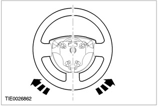
2.
NOTE: Make sure the drive wheels are pointing straight ahead.
Center the steering and lock it in this position.
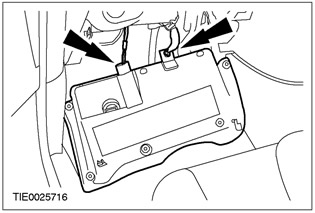
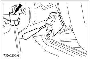
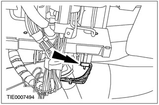
3. Disconnect the bottom section from the panel of devices.
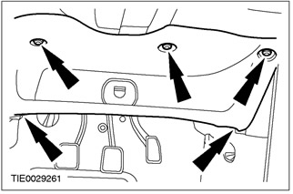
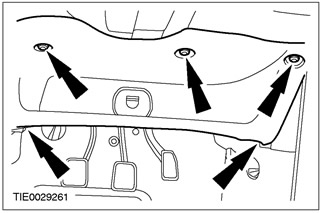
4. Remove the lower section of the instrument panel.
- Disconnect the data link connector (DLC).
- Disconnect the connector for the footwell light (in the presence of).
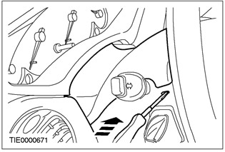
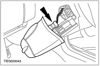
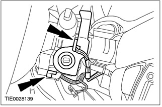
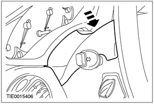
5. Remove the top casing of a steering column.
- Using a fine tip screwdriver, release the two clips (one on each side).
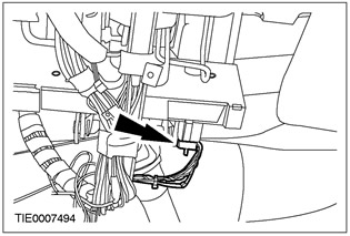
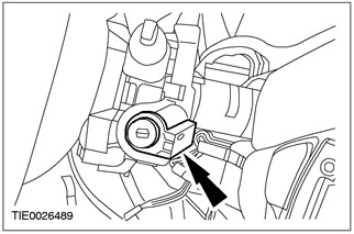
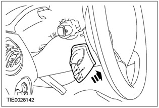
6. Disconnect the audio control switch from the lower casing of the steering column (in the presence of).
- Using a fine tip screwdriver, release the locking element.
7. Remove the audio control switch (in the presence of).
- Disconnect the plug connector.
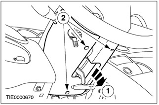
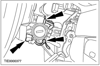
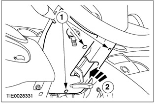
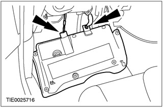
8. Remove the lower casing of a steering column.
- 1. Release the steering column lock lever.
- 2. Remove the screws.
Right hand drive vehicles
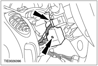
9. Remove the PAS transceiver (PATS).
- Disconnect the plug connector.

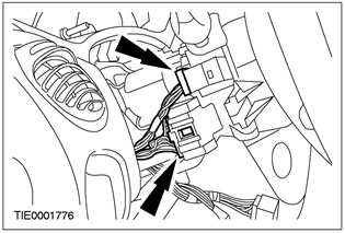
10. Disconnect the plug connectors for the wiper/washer switch, clock spring, and speed control system (in the presence of).
11. Disconnect the plug connectors of the ignition switch, direction indicators and headlight signaling.
Left hand drive vehicles
12. Disconnect the plug connectors of the transceiver of the passive anti-theft system (PATS), wiper/washer switch, clock spring and speed control system (in the presence of).
13. Disconnect the plug connectors of the ignition switch, direction indicators and headlight signaling.

Vehicles with yaw control
14. Disconnect the steering wheel rotation sensor connector.
All cars
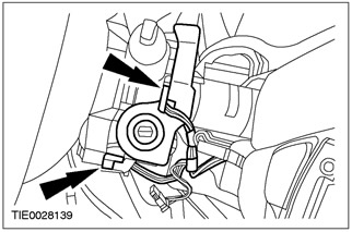
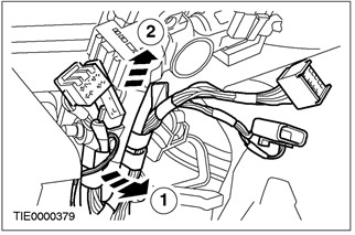
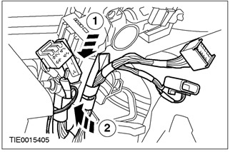
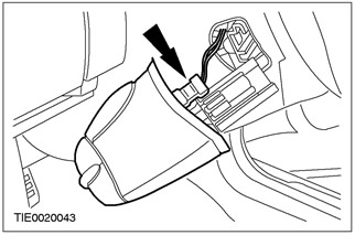
15. Disconnect the wiring harness from the steering column.
- 1. Release lock pin.
- 2. Disconnect the wiring harness.
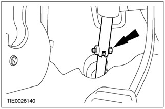
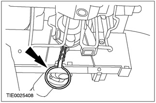
16. Disconnect the steering column shaft from the steering mechanism.
- Discard the bolt as it is no longer needed.
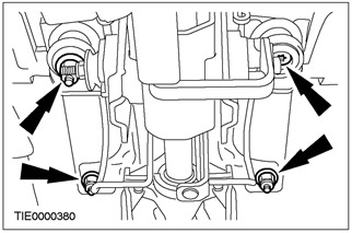
17. Remove the steering column.
Installation
All cars
1.
WARNING: New nuts must be used when installing the steering column. Failure to follow this instruction may result in injury.
NOTE: Make sure the drive wheels are pointing straight ahead.
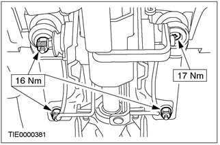
Install the steering column.
2.
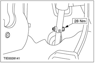
WARNING: Install a new steering column coupler bolt. Failure to follow these instructions may result in injury.
Connect the steering column shaft to the steering mechanism.
Vehicles with yaw control
3.
WARNING: If a new steering wheel rotation sensor is installed, the steering wheel rotation sensor lock pin must be removed. Failure to follow this instruction may result in injury.
Remove the pin.
All cars
4. Connect the wiring harness to the steering column.
- 1. Connect the wiring harness.
- 2. Install the dowel pin.
Vehicles with yaw control
5. Connect the steering wheel rotation sensor connector.
Left hand drive vehicles
6. Connect the plug connectors of the ignition switch, direction indicators and headlight signaling.
7. Connect the plug connectors of the PATS transceiver, wiper/washer switch, clock spring, and speed control system (in the presence of).

Right hand drive vehicles
8. Connect the plug connectors of the wiper/washer switch, clock spring and speed control system (in the presence of).
9. Install the PATS transmitter.
- Connect the electrical connector.
All cars
10. Establish the lower casing of a steering column.
- 1. Screw in the screws.
- 2. Lock the steering column lock lever.
11. Connect the audio control switch connector (in the presence of).
12. Set the audio control switch (in the presence of).
13. Establish the top casing of a steering column.
14. Connect DLC plugs and footwell lights (in the presence of).
15. Connect the lower section to the instrument panel.
16. Install the driver's airbag module. See Section 501-20A / 501-20B for more information.
Vehicles with yaw control
17.
WARNING: Reconfiguration of electronic heading stability is required. Failure to follow this instruction may result in injury.
Using WDS, configure the electronic heading stability function.
Visitor comments