- Electric drill
- Stud remover
| Name | Specification |
| Grease for joints of equal angular velocities (high temperature) | ESP-M1C207-A |
Disassembly
Right hand drive vehicles
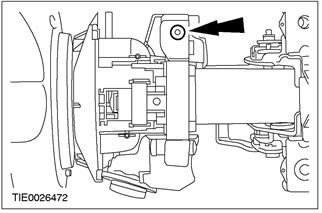
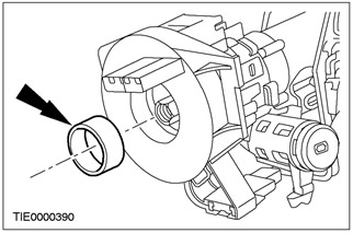
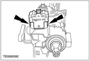
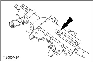
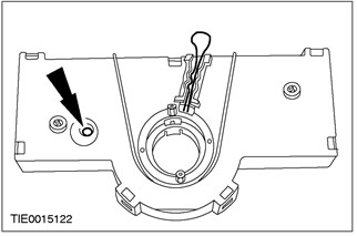
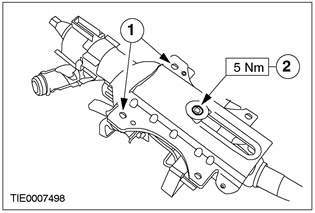
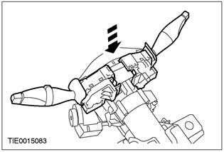
1. Using a tool such as an electric drill and a stud remover, remove the top ignition switch cover bolt.
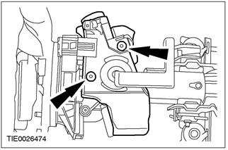
2. Using a tool such as a power drill and a stud remover, remove the ignition switch cover.
All cars
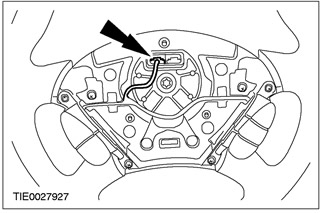
3. Disconnect the speed control connector (in the presence of).
4. Remove the steering wheel.
5. Remove the spacer.
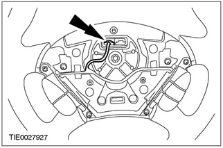
6.
CAUTION: Make sure that the clock spring cannot rotate. Secure in the center position using a piece of suitable tape.
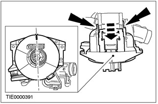
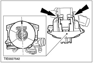
Remove the clock spring.
- Using a fine tip screwdriver, release the two retaining clips.
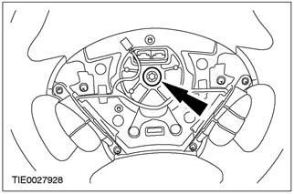
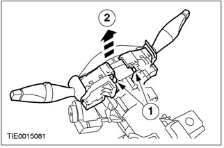
7. Remove the steering column multifunction switches.
- 1. Press the locking elements.
- 2. Pull the switches up.
8. Remove the PAS transceiver (PATS).
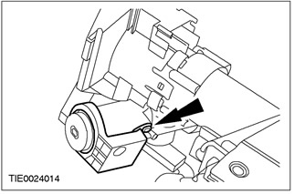
9. Remove the ignition switch. Release the locking tabs.
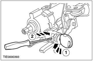
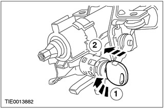
10. Remove the ignition switch lock cylinder.
- 1. Insert the ignition key and turn it to position I.
- 2. Using a fine tip screwdriver, press the stopper.
Vehicles with yaw control
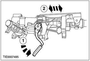
11. Fully extend the steering column.
- 1. Release the lock lever.
- 2. Pull out the steering column.
12.
NOTE: Before separating the steering column sections, mark them to facilitate subsequent installation.
Mark the two sections of the steering column.
All cars
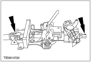
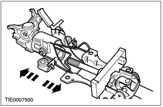
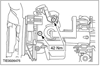
13. Turn out a bolt of a steering column.
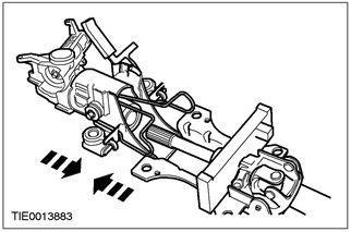
14. Separate the two sections of the steering column.
Vehicles with yaw control
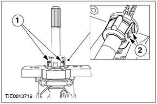
15. Remove the steering wheel rotation sensor clip.
- 1. Remove the screws.
- 2. Press the locking tabs.
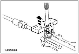
16. Turn out screws of fastening of the gauge of rotation of a steering wheel.

17. Remove the steering wheel rotation sensor.
Assembly
Vehicles with yaw control
1.
WARNING: Do not install a new steering wheel sensor if the lock pin has been removed. Failure to follow this instruction may result in injury.
WARNING: Before installing the steering wheel rotation sensor, make sure the sensor rotor is in the correct position. Failure to follow this instruction may result in injury.
Check the position of the steering wheel rotation sensor.
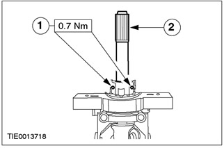
2.
WARNING: Make sure the steering wheel rotation sensor mounting screws are not over tightened. Failure to follow this instruction may result in injury.
Install the steering wheel sensor.
3.
WARNING: Make sure that the steering wheel rotation sensor clamp mounting screws are not overtightened. Failure to follow this instruction may result in injury.
Install the steering wheel rotation sensor clamp.
- 1. Install the screws.
- 2. Apply a lubricant such as CV joint grease (high temperature)
All cars
4.
NOTE: Make sure the steering column shafts are properly aligned.
Connect the two sections of the steering column.
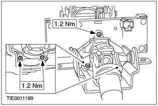
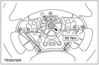
5.
WARNING: Make sure there are split grommets in the bracket holes. Failure to follow this instruction may result in injury.
WARNING: Make sure that the bolt torque is not exceeded. Failure to follow this instruction may result in injury.
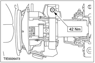
Tighten the steering column bolt.
- 1. Align the split bushings.
- 2. Tighten the steering column bolt.
6. Install the ignition switch lock cylinder.
- 1. Insert the lock cylinder.
- 2. Install the ignition switch lock.
7. Install the ignition switch.

8. Install the PATS transmitter.

9.
WARNING: Improper centering can result in premature element failure. If there is any doubt about the centering of the clock spring, repeat the centering procedure. Failure to follow this instruction may result in injury.
NOTE: After centering the clock spring, check that it cannot be rotated. Secure it with a suitable tape in the center position.
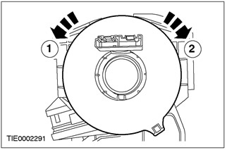
Center the clock spring.
- 1. Turn the clock spring in the COUNTER-CLOCKWISE direction just enough to feel resistance (approximately 2.5 turns from the center position).
- 2. Turn the airbag slider in a CLOCKWISE direction 2.5 turns until the arrow symbol in the center of the slider aligns with the raised "V"-shaped plot in position "12 hours" on the outer cover of the sliding contact. The clock spring is now centered.
10.
CAUTION: Be sure to install the spacer washer correctly. Do not assemble if spacer washer is missing.
Install the clock spring.
- Make sure both locking tabs are secured in the desired position on the steering column.
11. Install the steering column multifunction switches.
12. Remove the tape from the clock spring.
13. Install the steering wheel.
14. Connect the speed control connector (in the presence of).
Right hand drive vehicles
15.
NOTE: The ignition lock housing bolts are designed to shear when a certain torque is reached.
Install the ignition switch cover.
16.
NOTE: The ignition lock housing bolts are designed to shear when a certain torque is reached.
Install the top ignition switch cover bolt.
Visitor comments