Withdrawal
WARNING: To avoid the risk of accidental deployment, the backup power supply of the airbag control module must be discharged. After disconnecting the wire (ov) battery ground before making any repairs or adjustments to the auxiliary restraint system of the airbag and seat belts (SRS) or any element (ov), next to the SRS sensors, wait at least one minute. Failure to follow these instructions may result in injury.
WARNING: To minimize the risk of premature deployment of the airbag, do not use radio key code savers when operating the secondary restraint system. Failure to follow this instruction may result in injury.
WARNING: Never touch the tester probes to the electrical connectors of the airbag modules or any other element of the auxiliary restraint system. Failure to follow this instruction may result in injury.
WARNING: Make sure the front wheels are pointing straight ahead.
CAUTION: A new clock spring is shipped centered and has a red seal. When installing a new clock spring, break this red seal. If installing an existing clock spring, follow the centering procedure.
1. Remove the steering wheel. Refer to Section 211-04 for more information.
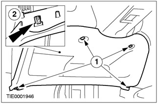
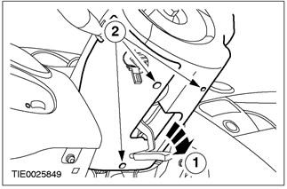
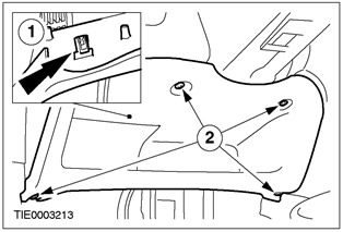
2. Disconnect the bottom section of the instrument panel from the instrument panel.
- 1. Remove the screws.
- 2. Release the clip.
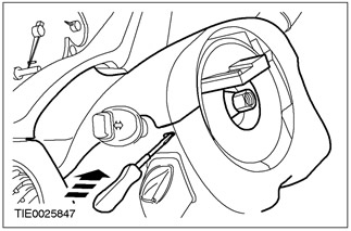
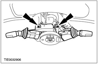
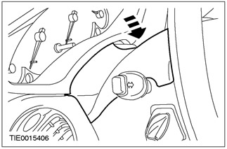
3. Disconnect the top casing of a steering column from the bottom casing of a steering column.
- Using a thin screwdriver, release the two clips (one on each side).
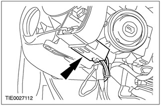
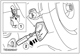
4. Disconnect the audio control switch from the lower casing of the steering column (in the presence of).
- Using a thin screwdriver, release the locking tab.
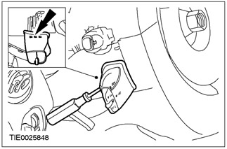
5. Remove the audio control switch (in the presence of).
- Disconnect the plug connector.
6. Remove the lower casing of a steering column.
- 1. Release the steering column lock lever.
- 2. Remove the screws.
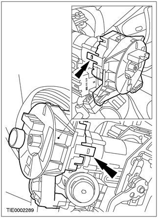
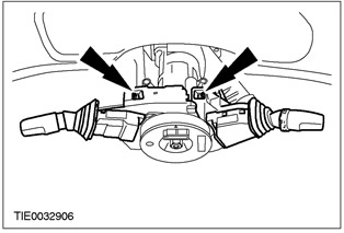
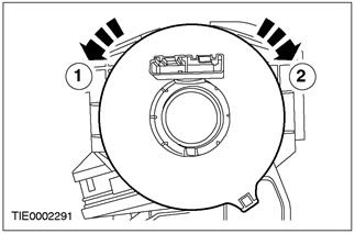
7. Disconnect the multi-function switches from the clock spring and place them aside.
- Click on the blocking elements in turn and slide each switch up.
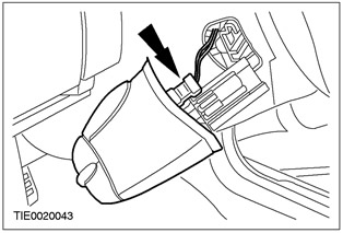
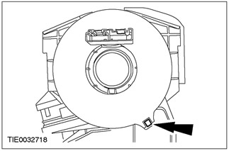
8. Disconnect the plug connector of the clock spring.
- Using a thin screwdriver, release the locking tab.

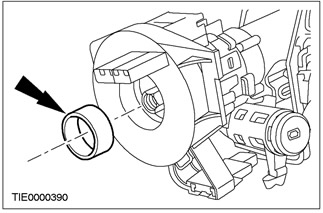
9.
CAUTION: Mark the position of the spacer in the center of the clock spring.
Remove the clock spring.
- Disconnect the fixing tabs from the steering column.
Installation
WARNING: Never touch the tester probes to the electrical connectors of the airbag modules or any other element of the auxiliary restraint system. Failure to follow this instruction may result in injury.
1. Install the clock spring.
- Make sure the locking tabs are secured in the desired position on the steering column.

2.
NOTE: A click will be heard when the locking tabs are properly and completely engaged.
Connect the plug connector of the clock spring.
3.
NOTE: A click will be heard when the locking tabs are properly and completely engaged.
Connect the multifunction switches to the clock spring.
4. Establish the lower casing of a steering column.
- 1. Install the screws.
- 2. Fix the blocking lever of a steering column.

5.
NOTE: A click will be heard when the locking tabs are properly and completely engaged.
Set the audio control switch (in the presence of).
- 1. Connect the audio control switch connector.
- 2. Set the audio control switch.
6. Establish the top casing of a steering column.
7. Connect the lower section of the instrument panel to the instrument panel.
- 1. Lock the clamp.
- 2. Install screws.
8.
WARNING: Do not turn the new clock spring between breaking the red seal and installing the steering wheel. If the vehicle has been left unattended by a mechanic between the opening of the red seal and the installation of the steering wheel, perform the centering procedure.
Break the red seal if necessary.
9.
WARNING: Improper centering can result in premature element failure. If in doubt while centering the clock spring, repeat the centering procedure. Failure to follow this instruction may result in injury.
WARNING: Make sure the front wheels are pointing straight ahead.
Center the clock spring.
1. Turn the clock spring counterclockwise until you feel resistance.
2. Turn the clock spring in a clockwise direction until the arrow on the clock spring rotor aligns with the raised symbol «V», which is located in the position «12 hours» on the outer cover of the clock spring (approximately two and a half turns).
10.
CAUTION: When installing the steering wheel, make sure that the spacer sleeve is in the correct position. Do not install steering wheel if spacer is missing.
Install the spacer.
11.
CAUTION: If the vehicle has been left unattended by a mechanic between the clock spring centering and steering wheel installation procedures, the centering procedure must be repeated.
Install the steering wheel. Refer to Section 211-04 for more information.
Visitor comments