Fuel burner
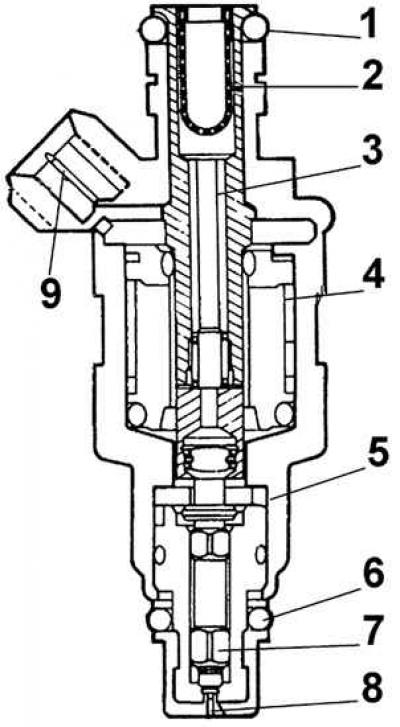
1 - sealing ring, 2 - inlet filter, 3 - armature, 4 - coil winding, 5 - housing, 6 - sealing ring, 7 - needle valve, 8 - nozzle needle, 9 - electrical contact
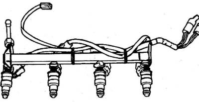
Fuel line and injectors
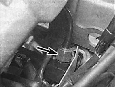
The location of the fuel line bolts on the V6 engine
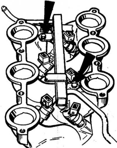
Bolts of fastening of a fuel highway are specified by arrows.
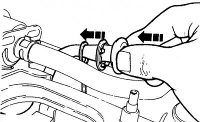
Removing the fuel injector from the line
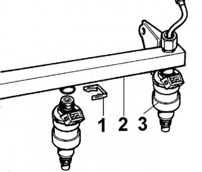
1 - retaining clip, 2 - fuel line, 3 - fuel injector
Fuel injector with seals removed
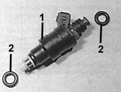
1 - fuel injector, 2 - seals
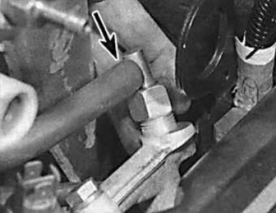
The union of giving of fuel on a fuel highway
The fuel supply fitting is indicated by an arrow.
OHC and V6 engines 2.8 in.3
1. Remove ground wire from battery.
2. On V6 engines, remove the throttle connection cover, which is secured with three screws.
3. Remove the line connecting the air flow meter to the intake manifold.
4. On ONS engines, remove the distributor cap and place it aside. If necessary, remove high voltage wires.
5. Disconnect the connector from the idle speed valve, throttle position sensor, and coolant temperature sensor.
6. On V6 engines, disconnect the throttle cable from the fuel pressure regulator bracket.
7. Slowly disconnect the vacuum and fuel lines from the fuel pressure regulator and the fuel supply connection from the fuel line.
8. Remove the overpressure chamber and throttle body.
9. Disconnect the fuel injector wires.
10. Unscrew the fuel bracket and remove it together with the fuel injectors.
11. O-rings and retaining clips on all fuel injectors must be replaced, even if only one fuel injector needs to be removed from the line. The bottom O-ring is installed between the thick and thin washers at the end of the injector.
12. Installation is made in sequence, return to removal. Lubricate sealing rings with Ford-ESEM 1C171A silicone grease. Check CO content.
DOHC engines
13. Remove ground wire from battery.
14. To improve access, remove the connector from the intake air temperature sensor, the high voltage wires and the accelerator cable or move them to the side.
15. Slowly loosen the fuel supply connection to the fuel system pressure relief line and disconnect the hose.
16. Remove fuel return hose (indicated by an arrow) from the highway.
17. Remove the vacuum tube from the top of the pressure regulator.
18. Remove the connectors from the fuel injectors and temperature sensor.
19. Unscrew the two mounting bolts and remove the fuel line.
20. Remove fuel injectors from cylinder head.
21. O-rings and retaining clips on all fuel injectors must be replaced, even if only one fuel injector needs to be removed from the line. The bottom O-ring is installed between the thick and thin washers at the end of the injector.
22. Installation is made in sequence, return to removal. Lubricate sealing rings with Ford-ESEM 1C171A silicone grease. Check CO content.
Engines V6, 2.4 and 2.9 dm3
23. Remove ground wire from battery.
24. Remove the line connecting the air flow meter to the intake manifold.
25. Disconnect the link arm from the throttle body and unscrew the 2 bolts securing the throttle cable bracket.
26. Disconnect the vacuum tubes, crankcase ventilation valve and fuel pressure regulator from the throttle body.
27. Disconnect the connectors from the throttle position sensor, engine and coolant temperature sensors, and the idle speed control valve.
28. unscrew 6 bolts "Togh", that secure the intake chamber.
29. Slowly loosen the fuel rail fuel supply connection to relieve pressure in the fuel system.
30. Disconnect the fuel line fuel supply pipe and the fuel return pipe.
31. Remove the fuel line mounting bolts and remove the line.
32. Remove the mounting clips and remove the fuel injectors from the line.
33. O-rings and retaining clips on all fuel injectors must be replaced, even if only one fuel injector needs to be removed from the line. The bottom O-ring is installed between the thick and thin washers at the end of the injector.
34. Installation is made in sequence, return to removal. Lubricate sealing rings with Ford silicone grease - ESEM 1C171A. Check CO content.
35. On engines with an early release fuel pressure regulator, if necessary, connect a new fuel inlet pipe to the line. The new connector comes with a control grip ring and allows you to keep the connector prongs retracted. When the two halves of the connector are pressed together, the ring pops out, indicating that the connection was successful.
36. Turn on the ignition 5 times without turning on the engine starter to increase the pressure in the fuel system.
Visitor comments