Depending on the year of manufacture and equipment, electrical wires, possibly vacuum and coolant hoses, may be routed and connected in the engine compartment in different ways. Since it is impossible to dwell on each option separately, mark the corresponding wires with adhesive tape before removing them. The following describes the removal of a gasoline engine with a manual transmission.
Withdrawal
Disconnect the ground wire (-) from the battery.
Attention! As a result, data in electronic storage devices, such as an engine fault memory or a radio code, are erased. Please read the section carefully "Removing and installing the battery", before disconnecting it.
Remove the air filter and air intake pipe, see point 5.6.
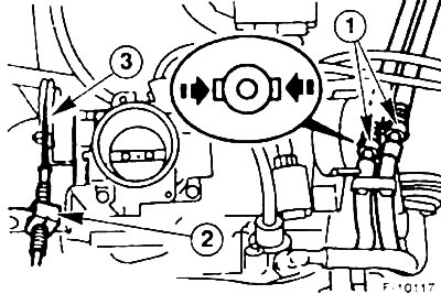
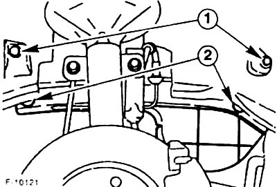
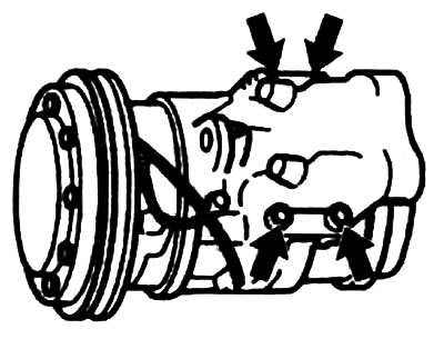
Squeeze the plastic tabs on the fuel supply lines -1- and remove the fuel lines. When removing the fuel line, it is necessary to wrap the latter with a rag so that the fuel flowing from it cannot be splashed. The fuel lines must be closed with suitable plugs, for example, a clean screw of suitable diameter can be inserted as a plug. To facilitate installation, mark the fuel lines with adhesive tape when removed.
Attention! Remove the fuel lines carefully so that the pressure in the fuel system is released gradually.
Remove a clip -2- and disconnect draft of gas.
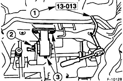
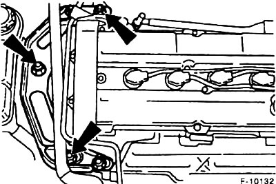
Disconnect the plug -1- of the power steering pressure switch. Unscrew the pressure pipe bracket -2- from the engine.
Unscrew the ground wire from the engine lifting lug.
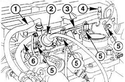
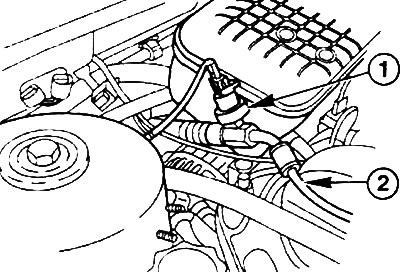
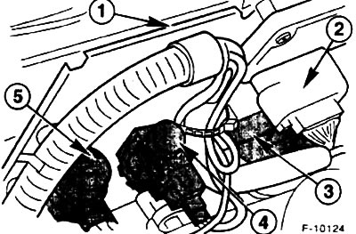
Remove vacuum hoses from fuel pressure regulator -2- and suction pipe. The figure also shows: 1 - fuel return hose; 3 - distribution pipe; 4 - valve; 5 - plug for jet; 6 - fuel supply.
Remove vacuum hoses from exhaust gas recirculation valve -4-, -3- at measuring point -2- of pipe -1-. Remove the engine ventilation hose near the ignition coil.
From the underside of the vehicle, remove the vacuum hose from the pulse air control valve -5-.
Unscrew the front exhaust pipe from the exhaust manifold. Release the exhaust system from all suspensions and remove it, see point 8.
Unscrew the lining of the wheel arch -1-, remove the protective cover of the belt pulley -2-.
Remove the V-belt see paragraph 1.19.
Disconnect the ground wire from the gearbox.
Disconnect the clutch release linkage from the shift lever.
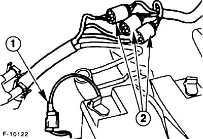
Disconnect the plug -1- and the multi-pin plug of the engine wiring harness -2-.
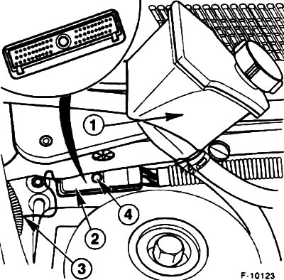
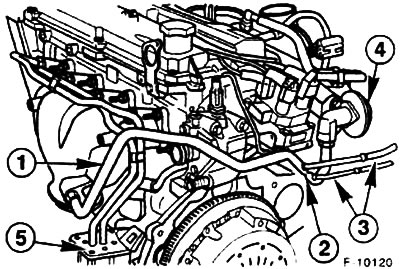
Pull the receiver -1- of the power steering upwards from the holders. Unscrew the ground wire -3-. Unscrew the bolt -4-, disconnect the plug -2- from the engine control unit.
On the bracket -1- on the front wall, disconnect the ignition module wire plug -2- (only in models with automatic transmission), differential pressure converter -3-, solenoid valve for pulsed air supply -4- and vacuum regulator -5-. Disconnect the wire bundle from the front wall.
Unscrew the heat shield from the exhaust manifold.
Raise the car on the goats.
Drain the oil see point 10.6.
Drain the coolant see point 3.3.
Loosen the hose clamps and remove the lower coolant hose from the radiator. On vehicles with an oil cooler, also disconnect the coolant hoses from the oil filter flange.
Loosen the hose clamps and remove the coolant hoses from the thermostat, see point 3.5.
Remove the pressure hose and expansion tank hose from the power steering pump. Collect the escaping hydraulic fluid in a container. Remove the hydraulic power steering pump, see point 13.4.
Cars with air conditioning
Attention! The air conditioning coolant circuit must not be opened. The coolant contains ingredients that can cause frostbite if it comes into contact with the skin. It is possible to remove the engine without opening the coolant circuit.
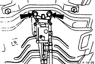
Unscrew the fixing bolts (arrows in the picture) air conditioner compressor (do not disconnect hoses) and thus suspend it with a wire so that it does not interfere with the dismantling process, the hoses must not be taut. Disconnect the magnetic coupling plug.
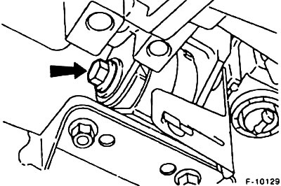
Disconnect the brake booster hose from the intake manifold. To do this, press the retaining clip on the suction manifold slightly into the manifold and hold it in this position, carefully pull the vacuum hose out of the spring sleeve.
Remove the left and right driveshafts, see 11.8.
Loosen the shift rod fixing bolt. Unscrew the shift fork rod and its support from the gearbox.
Unscrew the heat shield of the shift lever. Pull the shift levers back and tie them with a wire at the top to the body carrier frame.
Unscrew the bolts, remove the air conditioner dryer (where there is) and tie it with wire to the supporting frame of the body.
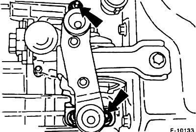
Unscrew the fixing bolts -1- of the steering mechanism on the auxiliary frame.
Unscrew the central bolts -2- on the engine support points. Unscrew the bolts -3- and remove the bracket from the auxiliary frame.
Unscrew the engine support bracket from the gearbox.
Remove the center bolt on the front engine support bracket.
Support the subframe with a garage jack. Unscrew the mounting bolts, lower and remove the auxiliary frame.
Unscrew from the gearbox takhoval, located near the flange of the left drive shaft.
Support the gearbox with a jack, while using wooden blocks to exclude possible damage.
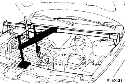
Raise the engine slightly with a winch or crane.
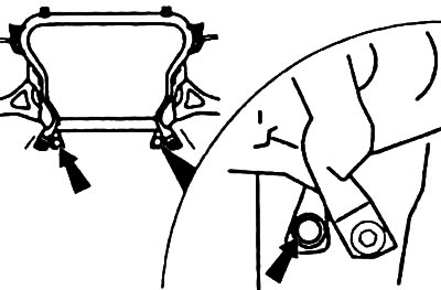
Right engine mount
Left engine mount
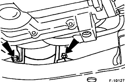
Unscrew the fixing nuts -arrows- of both engine mounts.
Make sure that all wires and hoses that come from the engine are removed.
Lower the block consisting of the engine and gearbox from the engine compartment down.
Installation
Check engine mounts and coolant, oil and fuel hoses for pores and cracks and replace if necessary.
Only new self-locking nuts may be used on engine mounts.
If the car has a high mileage, then the engine and gearbox must be disconnected. Check that the clutch release bearing rotates easily, check that the clutch release lever runs smoothly, replace them if necessary. Check whether the thickness of the friction lining on the clutch disc is sufficient, check the condition of the clutch, replace if necessary, see point 9.
Insert the block consisting of the gearbox and the engine from below into the engine compartment, make sure that the engine mounts are seated correctly.
Install the engine mount nuts, but do not tighten them yet.
Install the left and right propeller shafts, see 11.8.
Engage the brake booster vacuum hose in the snap lock on the intake manifold.
Vehicles with air conditioning: install the air conditioning compressor and tighten the bolts to 30 Nm.
Connect the lower coolant hose to the radiator, secure it with a spring clip. Instead of a spring clamp, a screw fastening clamp can be used.
Based on the markings made during dismantling, connect the coolant hoses to the coolant pump and thermostat, as well as to the oil cooler, secure the hoses with mounting clamps.
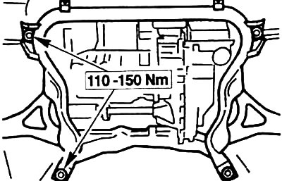
Using a jack, install the auxiliary frame, screw in the bolts, but do not tighten them. Orient the subframe correctly by inserting suitable drifts into the holes in the subframe and into the underbody of the vehicle. At this position, tighten the four subframe mounting bolts. Tightening torques 110-150 Nm. Take out the mandrels.
Remove voltage from the motor by shaking it. The engine must move freely in the front support.
Tighten the nuts of the right and left engine mounts with a torque of 90 Nm.
Remove the jack and crane.
Screw the rear engine mount to the gearbox with three bolts with a torque of 90 Nm.
Screw the rear engine support to the auxiliary frame, tightening torque of the bolts is 50 Nm. Tighten the central bolt of the engine support with a torque of 120 Nm, while the engine must not be pushed to the side. The support must not be under tension.
Tighten the steering gear mounting bolts to 130 Nm.
Tighten the central bolt of the front engine mount with a torque of 120 Nm.
Screw on the air conditioner dryer where it is.
Screw the shift levers, install the heat shield for the shift levers. Adjust the shift mechanism, see point 10.2.
Install the power steering pump, see point 13.4.
Screw on the heat shield for the exhaust manifold. At the same time, screw on the bracket for the coolant pipe and the oil level gauge.
Connect the main bundle of engine wires to the control device, tighten the fixing bolts. Screw the ground wire.
Install the power steering reservoir
Completely install the exhaust system, see point 8.3.
Lower the car on wheels
Install all electrical wires and vacuum hoses according to the markings made during dismantling, tighten their fasteners. Screw the ground wire to the gearbox.
Install the throttle.
According to the marking made during the dismantling process, connect the supply and return fuel lines, snap the quick connector.
Connect the ventilation hose to the cylinder head.
Install the V-belt see paragraph 1.19.
Install the belt pulley cover.
Connect the clutch rod and adjust the clutch. see point 9.3.
Install the air filter and air intake pipe, see point 5.6.
Fill oil into the engine and gearbox, see paragraphs. 10.6, 28.1.1.
Check if the coolant contains antifreeze and fill it up, see point 3.3.
Establish the lower facing of a radiator.
Fill the hydraulic power steering reservoir with hydraulic fluid, bleed the hydraulic power steering see 28.4.5.
Connect ground wire (-) to the battery. Set the clock and set the anti-theft code for the radio.
Warm up the engine to operating temperature, check fluid levels everywhere, check all connections for leaks.
Adjust the camber/toe of the front wheels (work being done in the workshop).
Visitor comments