Contents: Removal ↳ Installation ↳
Removal
Note: If only the seals need to be replaced, it is not necessary to remove the driveshaft assembly, see the relevant section.
Loosen the axle nut on the vehicle standing on its wheels, see item 11.6.
Mark the position of the wheels on the hub with paint so that they can be installed in the same place during assembly. Loosen the wheel nuts on the lowered car. Raise the front of the car and remove the front wheels.
Remove the brake caliper, see paragraph 15.2.
Hang the brake caliper on the inner mudguard with a wire, making sure not to twist or stretch the brake hose. The brake hose remains connected, otherwise you will have to bleed the brake system after installation.
Where necessary, disconnect the brake pad wear indicator multi-pin plug.
Disconnect the stabilizer bar connecting rod.
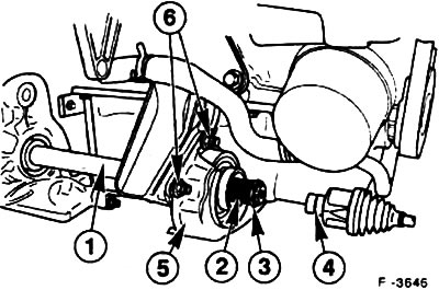
Press out the pin "3" of the transverse steering rod from the steering knuckle "1", see item 13.3.
Where necessary, remove ABS sensor "5" from the steering knuckle.
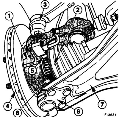
Remove the brake disc "4", see item 15.4.
Unscrew the clamp bolt "8" and the ball joint nut "6" of the lower transverse arm "7" and pull the transverse arm down from the steering knuckle.
Caution: Do not damage the ball joint seal. Wrap it in a cloth to protect it.
Remove the shock absorber strut mounting clamp bolt on the steering knuckle.
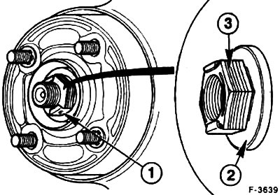
Unscrew the axle nut "1". The self-locking axle nut "3" with the freely rotating washer "2" can be reused up to five times.
Use a puller to press the steering knuckle off the cardan shaft.
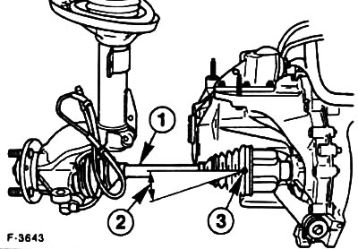
Pull the steering knuckle outward and remove the cardan shaft from the steering knuckle. In order to avoid unwanted loading of the inner joint, hang the cardan shaft "1" on a wire. The maximum permissible angle of inclination of the inner joints is 18°. The outer joint has a stop, but it must not be pressed when stopped.
Left cardan shaft
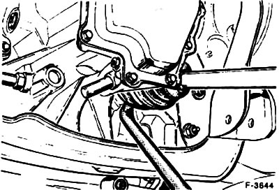
If you need to remove the driveshaft assembly, place a large pry bar between the joint and the gearbox housing. Turn the pry bar and remove the joint.
Attention! To avoid damage to the box, place wooden spacers underneath. Do not pull on the cardan shaft!
Right cardan shaft
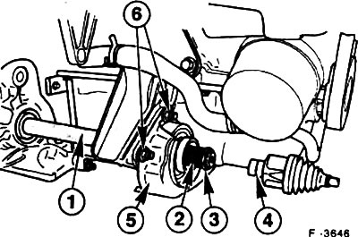
Remove bolts "6" of the middle support.
Remove the heat-protective cover "5". Replace the damaged one-piece cover (manufactured before 6/93) with a new one consisting of two parts.
Pull the driveshaft.
Installation
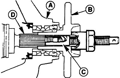
Before installation, check the condition of the propeller shaft sealing ring.
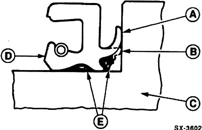
A - petal of a new sealing ring, B - worn petal, C - wheel hub or propeller shaft, D - sealing ring, E - grease.
Remove the worn sealing ring using a flat chisel.
Caution: Do not damage the gearbox housing.
Caution: If the sealing ring is defective or worn, check the condition of the rollers and bearing races.
Lubricate the new sealing ring as shown in the figure and press it evenly with a pipe of suitable diameter.
Right cardan shaft
Replace retaining ring "3".
Clean the splines "2" of the intermediate shaft "1" and thoroughly lubricate them over the entire surface with special FORD-SQM-1C9004-A grease (6-8 g).
Slide the propeller shaft on.
Left cardan shaft
Clean the splines and threads of the driveshaft and lubricate with a thin layer of grease.
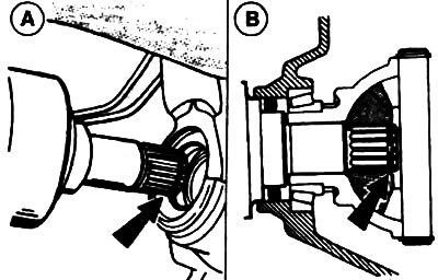
Insert the cardan shaft with a new locking ring "arrow A" into the splines of the leading spherical gear and secure it with strong pressure "arrow B". Check the reliability of the cardan shaft locking with light reciprocating movements.
Turn the steering knuckle outward and guide the driveshaft into the wheel hub bearings by hand. Install the washer, screw on the used wheel axle nut and pull out the driveshaft knuckle by screwing on the axle nut. Do not tighten the wheel axle nut. Finally, unscrew the axle nut and replace it.
Attention! If the axle nut cannot be screwed on, then tighten the hub to the stop using the special device FORD 14-041. During this process, turn the wheel hub to install the bearings correctly. Remove the device and screw the hub axle nut by hand to the stop, do not tighten the nut.
Insert the ball joint of the wishbone into the hole in the steering knuckle from below and tighten the clamp bolt to a torque of 80 Nm (on a new ball joint - to a torque of 55 Nm).
Screw in the ABS sensor, if removed, 10 Nm.
Install the brake disc and secure it with two new stoppers.
Install the brake caliper, see paragraph 15.2.
If the brake hose has come loose, remove air from the brake system, see item 15.12.
Connect the multi-pin plug of the brake pad wear indicator where required.
Attach the tie rod head to the steering knuckle and tighten to 25-30 Nm. Secure the connection with a new cotter pin. If the cotter pin does not fit into the hole, tighten the threaded connection until the cotter pin fits into the hole.
Tighten the anti-roll bar connecting rods to a torque of 50 Nm.
Install the front wheels so that the marks applied earlier match. Before installing the wheels, lubricate the centering surface on the wheel hub with a thin layer of grease. Screw on the wheel mounting nuts. Lower the car and tighten the nuts crosswise to a torque of 100 Nm.
Tighten the front axle nut to 340 Nm. To lock the wheels, apply the parking brake and have an assistant press the foot brake pedal.
Attention! The car must be on its wheels.
Check the brake hose and ABS sensor wire for freedom of movement. To do this, an assistant should turn the front wheels from one extreme position to the other.
Check the gearbox oil level, top up if necessary, see p. 10.6.
The original article is posted at: FORDBOOK.RU