Contents: Removal ↳ Installation ↳
Removal
Loosen the axle nut with the vehicle standing on its wheels, see item 11.8.
Mark the position of the wheels on the hub with paint so that they can be installed in the same place during assembly. Loosen the wheel nuts on the lowered car. Raise the front of the car and remove the front wheels.
Remove the brake caliper, see paragraph 15.2.
Hang the brake caliper on the inner mudguard with a wire, making sure not to twist or stretch the brake hose. The brake hose remains connected, otherwise you will have to bleed the brake system after installation.
Where necessary, disconnect the brake pad wear indicator multi-pin plug.
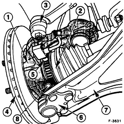
Press out the pin "3" of the transverse steering rod from the steering knuckle "1", see item 13.3.
Where necessary, remove ABS sensor "5" from the steering knuckle.
Remove the brake disc "4", see item 15.4.
Unscrew the clamp bolt "8" and the ball joint nut "6" of the lower transverse arm "7" and pull the transverse arm down from the steering knuckle.
Caution! Do not damage the ball joint seal. Wrap it in a cloth to protect it.
Loosen the shock absorber strut mounting clamp bolt on the steering knuckle.
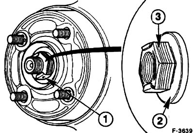
Unscrew the axle nut "1". The self-locking axle nut "3" with the freely rotating washer "2" can be reused up to five times.
Use a puller to press the steering knuckle off the cardan shaft.
Spread the knuckle clamp and remove the shock absorber strut. For this purpose, FORD service stations use tool 14-039.
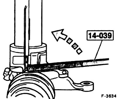
Insert the device into the groove of the steering knuckle, as shown in the figure, and turn the lever 90°, thereby releasing the shock absorber strut. For this operation, you can use a chisel or a suitable pry bar, paying attention not to damage the structural elements.
Installation
Insert the shock absorber strut into the steering knuckle. Remove the expanding device.
Install the new self-locking shock absorber clamp bolt, making sure the bolt fits through the slot in the mounting plate. Tighten the clamp bolt to 85 Nm.
Press the steering knuckle onto the cardan shaft, see item 11.8.
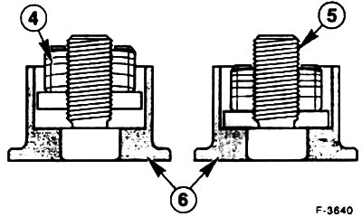
Screw on, without tightening, the self-locking nut of the axle "4" until it fits against the wheel hub "6".
Insert the ball joint of the control arm into the hole in the steering knuckle from below and tighten the clamp bolt to a torque of 80 Nm (on a new ball joint, to a torque of 55 Nm).
Screw in the ABS sensor, if removed, 10 Nm.
Install the brake disc and secure it with two new stoppers.
Install the brake caliper, see paragraph 15.2.
If the brake hose has come loose, remove air from the brake system, see item 15.12.
Connect the multi-pin plug of the brake pad wear indicator where required.
Attach the tie rod head to the steering knuckle and tighten to a torque of 25-30 Nm, secure the connection with a new cotter pin.
Install the front wheels so that the marks applied earlier match. Before installing the wheels, lubricate the centering surface on the wheel hub with a thin layer of grease. Screw on the wheel mounting nuts. Lower the car and tighten the nuts crosswise to a torque of 100 Nm.
Tighten the front axle nut to 340 Nm.
Note: the vehicle must be on its wheels.
Check the brake hose and ABS sensor wire for freedom of movement. To do this, an assistant should turn the front wheels from one extreme position to the other.