Withdrawal
Mark the position of the wheels on the hub with paint in order to install them in their original place during assembly. Loosen the wheel nuts with the vehicle lowered. Raise the front of the car and remove the front wheels.
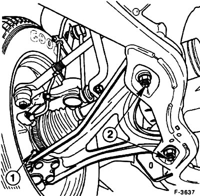
Unscrew the nuts -2- securing the transverse arm to the subframe.
Disconnect both anti-roll bar links.
Disconnect the tie rod ball pin from the steering knuckle, see point 13.3.
Remove the inner collar of the rubber cuff of the semi-axial cardan shaft.
Unscrew the nut and pull out the pin -1- of the ball joint.
Disconnect the transverse arm from the steering knuckle. If difficult, insert a pry bar between the transverse arm and vehicle frame and push the arm down.
Attention! to avoid damage during subsequent assembly, wrap the cuff of the semi-axial cardan with a rag.
Remove the transverse suspension arm.
Installation
Install the transverse link to the subframe. Align the holes and insert the bolts from above, screw the nuts by hand.
Attention! tighten the nuts when the vehicle is on wheels. To ensure that the bolts do not come into contact with the gearbox housing, insert them only from above.
Install the driveshaft and secure the cuff with a new clamp.
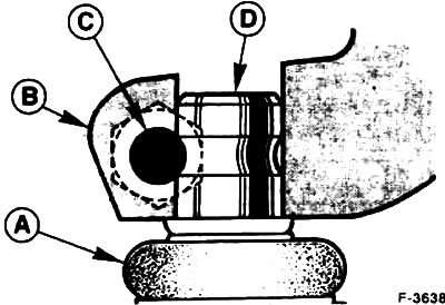
Insert the transverse arm into the steering knuckle until it stops. Insert the pin -C- from the front, it should enter the slots of the steering knuckle pin.
Attention! the head of the bolt must face forward in the direction of travel.
Tighten the pin nut with a torque of 80 Nm (when installing a new finger - 55 Nm). In this case, the finger should not rotate. A - rubber cuff, B - steering knuckle, D - ball joint trunnion.
Insert the tie rod pin into the steering knuckle and secure with a nut with a torque of 25-30 Nm, lock the nut with a new cotter pin. Insert the cotter pin into the finger hole and bend the ends. If the cotter pin does not fit into the hole, tighten the threaded connection until the cotter pin enters the hole.
Tighten the stabilizer linkages to 50 Nm.
Install the front wheels so that the marks made earlier coincide. Apply a light coat of grease to the centering surface on the wheel hub before installing the wheels. Screw on the wheel nuts. Lower the vehicle and tighten the nuts crosswise to 100 Nm.
Tighten the threaded connection of the transverse arm to the subframe. First loosen the nuts completely, and then tighten in four steps (keep the bolts from turning):
- 1st step: Tighten the nut with a torque wrench to 50 Nm.
- 2nd step: Loosen the nuts completely.
- 3rd stage: Tighten the nuts with a torque of 50 Nm
- Step 4: Tighten the nuts 90°with a hard wrench (1/4 turn) in one go.
Attention! the vehicle must be on wheels.
Visitor comments