Withdrawal
Mark the position of the wheels on the hub with paint in order to install them in their original place during assembly. Loosen the wheel nuts with the vehicle lowered. Raise the front of the car and remove the front wheels.
Disconnect the brake hose holder from the shock absorber.
Remove the brake caliper see point 15.2.
Hang the brake caliper with wire from the inner mudguard, taking care not to twist or pull the brake hose. The brake hose remains connected, otherwise you will have to bleed the air from the brake system after installation.
Where necessary, disconnect the multi-pin connector of the brake pad wear indicator.
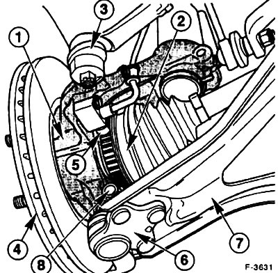
Press the pin -3- of the tie rod out of the steering knuckle -1-, see point 13.1.
Where necessary, unscrew the ABS sensor -5- from the steering knuckle.
Remove the inner collar of the inner rubber cuff of the semi-axial shaft.
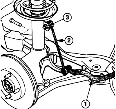
Unscrew the nut -3- and disconnect the connecting rod -2- of the anti-roll bar -1- from the shock absorber strut.
Turn out a tightening bolt -8- and a nut of a spherical support -6- of the lower cross-section lever -7- and pull down the cross-section lever from a rotary fist.
Attention! do not damage the collar of the ball stud. Wrap it in a rag to protect it.
Where required, disconnect the electronic damper adjustment plug and disconnect the wire from the shock absorber strut.
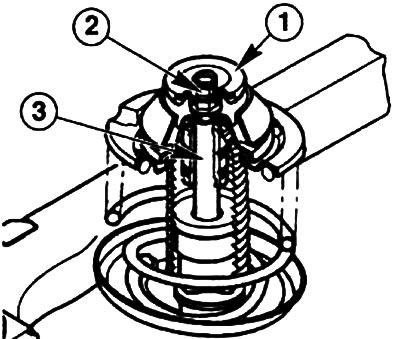
Remove the cap -1- of the shock absorber nut in the engine compartment.
Loosen the top strut mounting nut with an 18 mm ring wrench with a deep bend. When unscrewing, hold the shock absorber rod from turning with a 6 mm Allen key.
Remove the complete shock absorber strut, semi-axial driveshaft and steering knuckle.
Remove the shock absorber from the steering knuckle. To do this, unscrew the clamping bolt on the steering knuckle.
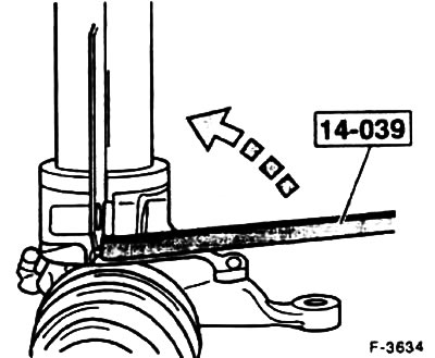
Extend the knuckle clamp and remove the shock absorber strut. To do this, a FORD service station uses tool 14-039. The device is inserted into the groove of the steering knuckle, as shown in the figure, and the lever is rotated 90°. thereby freeing the shock absorber. For this operation, you can use a chisel or a suitable pry bar, taking care not to damage the parts.
Installation
Insert the shock absorber into the steering knuckle. Remove the spreader.
Install the new shock absorber self-locking clamp bolt, making sure the bolt goes through the groove in the mounting plate. Tighten the clamping bolt to 85 Nm.
Install the shock absorber, axle shaft and steering knuckle.
Tighten the top strut nut by hand.
Install the semi-axial cardan shaft and secure the rubber cuff with a new clamp.
Insert the ball pin of the anti-roll bar connecting rod into the hole in the shock absorber strut and tighten to 50 Nm.
Insert the ball joint of the transverse arm from below into the hole of the steering knuckle and tighten the clamping bolt with a torque of 80 Nm (on a new ball joint - with a torque of 55 Nm).
Screw in, if removed, the ABS sensor, 10 Nm.
Attach the tie rod head to the steering knuckle and tighten with a torque of 25-30 Nm, lock the connection with a new cotter pin. If the cotter pin does not fit into the hole, tighten the threaded connection until the cotter pin enters the hole.
Connect, where necessary, the multi-pin plug of the electronic damper adjustment and fix the wire to the shock absorber strut.
Install the brake caliper see point 15.2.
If the brake hose is loosened, bleed the air from the brake system, see clause 15.12.
Connect, where required, the multi-pin connector of the brake pad wear indicator.
Attach the brake hose holder to the shock absorber.
Install the front wheels so that the marks made earlier coincide. Apply a light coat of grease to the centering surface on the wheel hub before installing the wheels. Screw on the wheel nuts. Lower the vehicle and tighten the nuts crosswise to 100 Nm.
Tighten the upper shock absorber nut to 45 Nm while holding the shock absorber rod from turning.
Check the freedom of movement of the brake hose and ABS sensor wire. To do this, the assistant must turn the front wheels from one extreme position to another.
Visitor comments