Contents: Removal ↳ Installation ↳
Leaky protective covers must be replaced immediately. To replace the protective covers, the cardan shaft must be disassembled. If dirt has gotten into the grease, wash the joint and lubricate it with new special grease.
Attention! Observe extreme cleanliness. Even minor contamination leads to destruction of the joint.
Lubricant specification: FORD-SQM-1C9004-A.
Amount of grease for the inner joint: 180 g.
Amount of grease for the inner joint: 100 g.
Damaged bearing balls lead to cyclic impact loads, which can be determined by the noise of the joint. In this case, the joint must be replaced.
Attention! On a car with high mileage, it is recommended to replace both rubber seals. Also replace both corrugated casings when removing the hinges.
Removal
Mark the position of the cuff with a marker.
Remove the shock absorber strut assembly with the steering knuckle and propeller shaft, see p. 11.1.
Attention! Be careful that the spherical rollers do not fall out.
Remove the spherical rollers.
Secure the driveshaft in a vice with protective jaws.
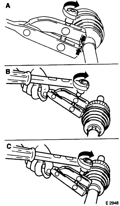
Remove the inner tripod joint, first removing the retaining ring with suitable pliers. Mark the position of the driveshaft with a felt-tip pen. In some circumstances, a puller is required for removal.
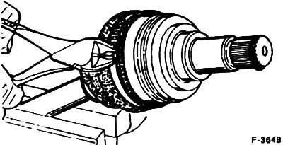
Cut the cuff fastening clamp with nippers and remove the clamp.
Remove the rubber cuff.
Installation
Lightly lubricate the surface of the cardan shaft to make it easier to insert the seal.
Press the outer sleeve into the annular groove of the joint. At the same time, insert a small screwdriver under the sleeve along the large diameter to release air from under the sleeve. Correct the position of the sleeve in accordance with the previously applied marking. Pay attention to the sufficiency of the joint lubrication.
Attention! Do not crimp the corrugated cover after installation.
Place the tension band in the annular groove of the cuff and tighten it with a special tensioner FORD-14-044, while tightening the tension bolt with a torque wrench to 20 Nm.
Place the inner sleeve on the shaft, adjust its position in accordance with the marking applied and secure it on the small diameter with tape with a torque of 20 Nm.
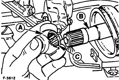
Inner joint: place Tripod "A" on cardan shaft "B" and lock with a new locking ring. Pay attention to the previously applied marking. Insert Tripod until it stops, use a pipe of suitable diameter if necessary.
Caution! Do not damage the installation locations of the constant velocity spherical rollers.
Install the constant velocity rollers, lubricated with special grease SQM-1C9004-A.
Install the shock absorber strut assembly with the steering knuckle and propeller shaft, see p. 11.1.
Place the cuff on the inner hinge. At the same time, insert a small screwdriver under the cuff to release air from under the cuff. Insert the Tripod hinge as far as it will go inward and pull it back 20 mm. In this position, remove the screwdriver. Adjust the position of the cuff in accordance with the previously applied marking. Pay attention to the sufficient lubrication of the hinge.
Install the front wheels so that the marks applied earlier match. Before installing the wheels, lubricate the centering surface on the wheel hub with a thin layer of grease. Screw on the wheel mounting nuts. Lower the car and tighten the nuts crosswise to a torque of 100 Nm.
Tighten the upper shock absorber nut to 45 Nm.
Check the brake hose and ABS sensor wire for freedom of movement. To do this, an assistant should turn the front wheels from one extreme position to the other.