The gearbox is removed downward. Removal requires a suitable lifting platform or viewing pit with a lift and wooden supports. The automatic transmission is removed basically in the same way as a mechanical one, pay attention to special instructions.
Withdrawal
Disconnect the ground wire (-) from the battery.
Attention! As a result, data in electronic storage devices, such as an engine fault memory or a radio code, are erased. Please read the section carefully "Removing and installing the battery", before disconnecting it.
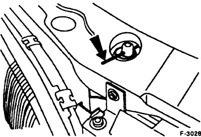
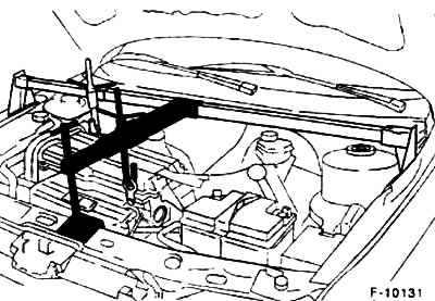
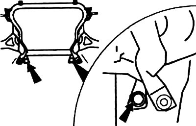
Fix the radiator at the top as the bottom mount is removable. For fixing, insert the wire into the upper radiator mount.
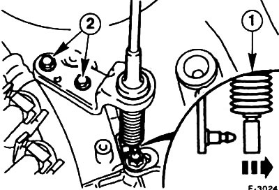
Loosen the suspension strut nuts by turning them five turns, do not completely unscrew the nuts. When unscrewing the shock absorber rod, hold it with an Allen key.
Remove the air filter and intake pipe, see point 5.6.
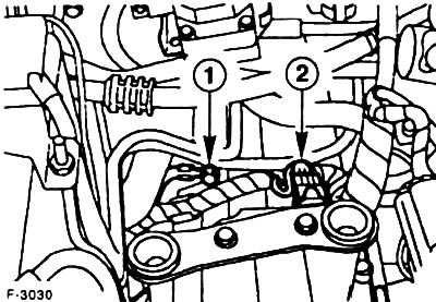
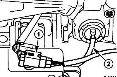
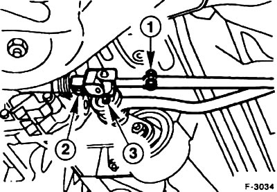
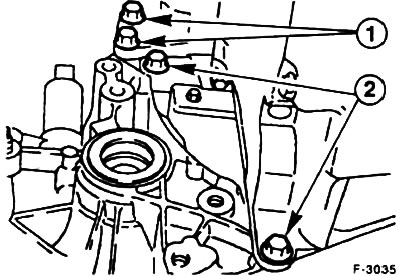
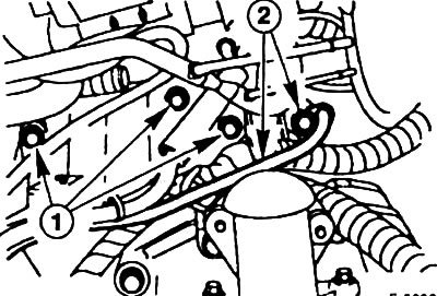
Disconnect the ground wire -1- on the gearbox.
Disconnect the plug -2- of the reversing light switch.
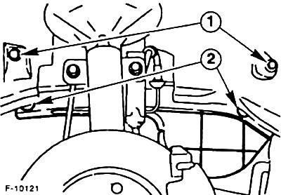
Disconnect the clutch cable from the lever -1-, while pushing the lever a little by hand in the direction of the cable.
Disconnect the cable from the holder -2- and put it aside.
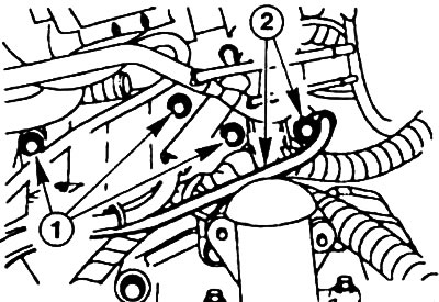
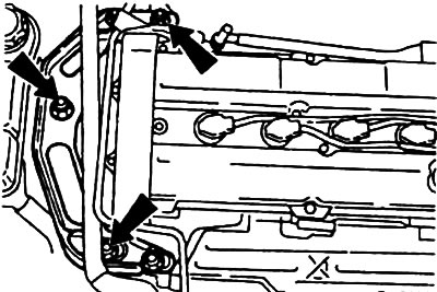
Remove the three upper flange bolts -1- engine/gearbox.
Turn out bolts -2- of the top fastening of a starter and wires of weight of the accumulator.
Remove the right and left semi-axial cardan shafts, see 11.8.
Turn out bolts of a casing of a wheel niche. Unscrew fastening -2- of the V-belt cover and remove it.
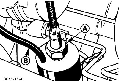
Unscrew the union nut -A- of the speedometer drive shaft, remove the shaft. Disconnect the connector of the wire connector -B- of the speedometer sensor.
Remove the lower radiator shroud.
Automatic transmission
Disconnect the oil inlet and outlet lines from the gearbox oil cooler and plug the holes with suitable plugs. Catch the leaking oil with a thick rag.
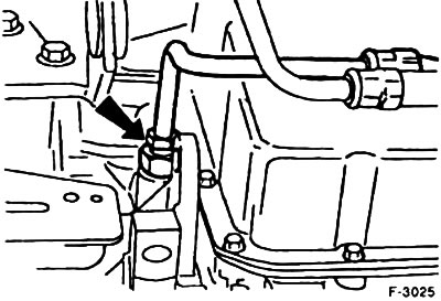
Attention! do not allow dirt to enter the oil circuit, as this will lead to a malfunction.
Disconnect the cable -1- of the mode selector lever. Turn out bolts of fastening of a countersupport.
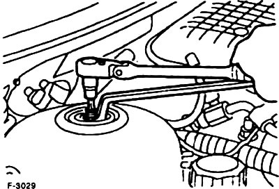
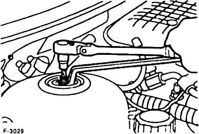
Turn out two bolts of fastening of a hatch of a flywheel and remove a hatch. Turn out through an aperture four nuts of fastening on the converter of the moment for what turn the crankshaft each time on 1/4 turn. To crank the engine, install the socket on the center bolt of the V-belt pulley on the crankshaft.
Remove the thermostat housing see point 3.5.
Disconnect the two multi-pin control plugs on the automatic box.
Disconnect the plug -1- of the Lambda sensor and disconnect the plug from the plate.
Disconnect the vacuum hose -2- from the filter of the impulse air system.
Disconnect the front exhaust pipe from the exhaust manifold. Disconnect the exhaust system from all suspensions and remove the system assembly, see point 8.
Place the shift lever in neutral position, the gear is disengaged.
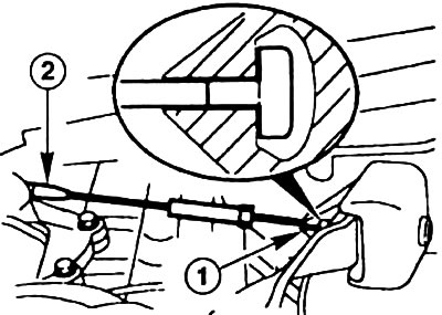
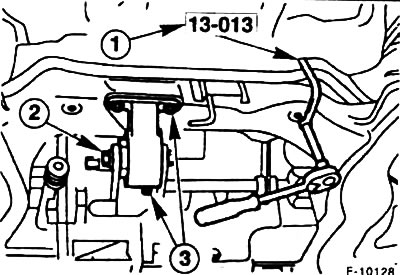
Disconnect the shift bar from the gearbox shift shaft, to do this, loosen the clamping bolt -1- and pull the shift bar -2-.
Turn out bolts -3- of the stabilizer of a bar of a gear change.
Turn out fastening of a thermal insulating guard of levers of switching. Turn the shift levers back and secure them with wire to the vehicle structure.
Turn out bolts, remove a dehumidifier of the conditioner (where installed) and fasten with wire to the car structure.
Turn out bolts of fastening of the steering mechanism on a stretcher.
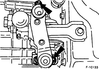
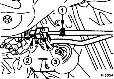
Turn out the central bolt -2- on a jet support of the engine. Turn out bolts -3- and remove an arm from a stretcher.
Turn out bolts of fastening of an arm of a jet support of the engine on a transmission.
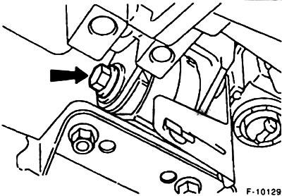
Turn out the central bolt of a forward jet support of the engine.
Support the subframe with a lift. Turn out bolts of fastening, lower and remove a stretcher.
Support the gearbox with a lift. Use wooden pads to avoid damage.
Attach the engine jack to the engine transport plate and lift it slightly with a crane.
Right engine mount
Left engine mount
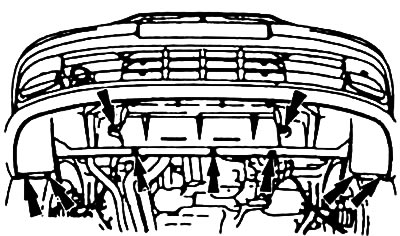
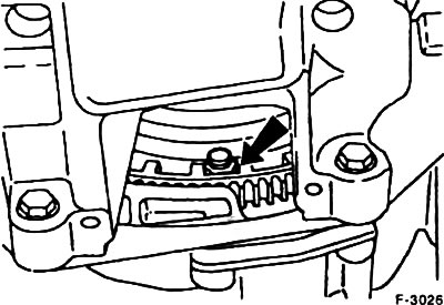
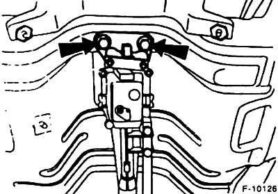
Unscrew both nuts -arrows- from the engine mounts.
Lower the power unit until the box is at the level of the left side member. On vehicles with air conditioning, lower the engine until until the A/C compressor is below the right side member.
Easily support the box on the lift.
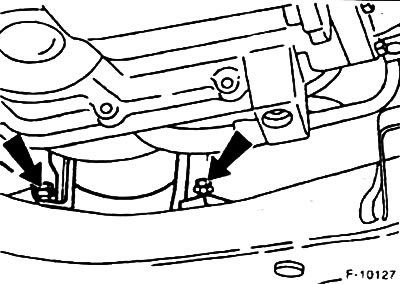
Turn out two bolts -1- of fastening of a starter and two lower flange bolts -2- of a transmission.
Lift the box with your hands, use a pry bar to disconnect it from the engine and then lower it down.
Installation
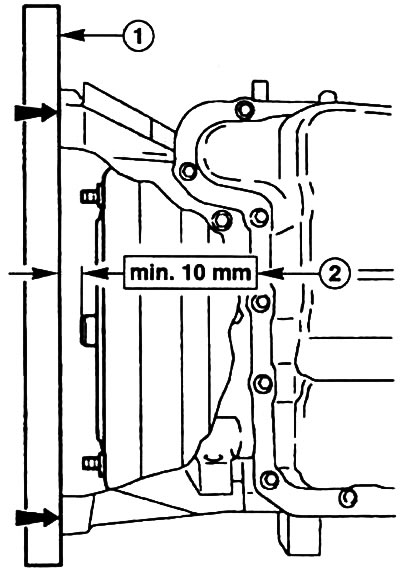
Automatic transmission: before installing, place a ruler -1- on the gearbox flange and measure the installation dimension of the torque converter. It must be at least 10 mm. During installation, do not change the installation size of the inverter. Pay attention to the correct position of the intermediate plate.
Attention! insufficient installation size of the torque converter leads to damage to the box and drive disk. The inverter will not connect optimally to the oil pump.
Before installing the gearbox, check the clutch and release bearing, see point 9.
Use new self-locking nuts for engine mounts. Replace any removed rings.
Clean and lubricate with a thin coat of Moly-Spray lubricant the transmission input shaft splines.
Attention! do not apply too much lubricant, as during operation it can get on the working surfaces of the clutch and disrupt its functioning.
Raise the gearbox and enter in a horizontal plane into the clutch. If the splines of the shaft do not fit into the splines of the clutch disc, then turn the drive shaft or crankshaft of the engine to the required amount.
Advance the gearbox until the holes in the clutch housing fit into the guide bushings.
Tighten the two lower gearbox flange bolts to 40 Nm. Fasten the starter with two bolts, tighten the bolts with a torque of 50 Nm.
Attention! do not tighten the gearbox to the engine by tightening the bolts.
Direct the power unit from below into the engine compartment, while making sure that the engine mounts are correctly positioned.
Install, but do not overtighten, the engine mount nuts.
Install and secure the speedometer drive shaft, connect the speedometer sensor plug.
Install the right and left side shafts, see 11.8.
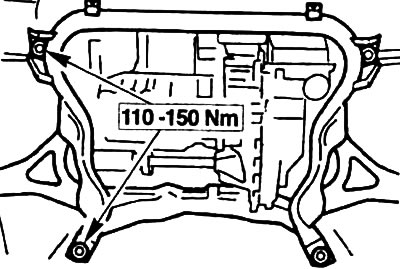
Establish a subframe, screw, without tightening, bolts. Adjust the position of the subframe with a suitable rod by inserting it into the hole in the subframe and bottom. Tighten the four bolts of the subframe in this position with a torque of 110-150 Nm. Take out the rod.
Correct the position of the power unit by rocking it, it should move freely on the front jet support.
Tighten the nuts of the left and right engine mounts to 90 Nm.
Disconnect the beam crane and remove the lift.
Secure the rear jet engine mount with three bolts to the subframe with a torque of 50 Nm. Tighten the reaction mount center bolt to 120 Nm without pushing the engine to the side. The support must not be under tension.
Tighten the steering gear mounting bolts with a torque of 130 Nm
Tighten the central bolt of the front jet engine mount with a torque of 120 Nm.
Attach the air conditioner dryer where required.
Install the shift lever heat shield.
Install shift levers. Tighten bolt -1- to 55 Nm, bolt -2- to 25 Nm. Do not tighten the clamping bolt, it must be tightened only after adjusting the shift.
Place the shift lever in neutral.
Install the complete exhaust system, see point 8.
Connect the plug of the lambda sensor and attach the plug to the plate.
Connect the suction hose of the air-pulse filter.
Install the lower radiator shroud.
Install the V-belt pulley cover.
Screw in and tighten to 40 Nm the top three engine/gearbox flange bolts.
Wrap and tighten with a torque of 50 Nm the bolts -2- of the upper mounting of the starter and the battery ground wire.
Remove the retaining wire from the upper radiator support.
Connect the cable and adjust the clutch, see point 9.3.
Attach the engine/gearbox ground wire to the gearbox.
Connect the reversing light switch connector.
Tighten the nuts of the right and left suspension struts with a torque of 50 Nm, while holding the shock absorber rod from turning.
Install the air filter and intake pipe, see point 5.6.
Check the laying of the vacuum hose and wires, fix with holders if necessary.
Adjust the gear shift see point 10.2.
Automatic transmission
Attach and fix the oil lines of the oil cooler box with a torque of 25 Nm.
Install the four torque converter nuts, turning the motor 1/4 turn each time. To crank the engine, install a head on the central bolt of the crankshaft pulley. Install the flywheel cover.
Install the thermostat housing and fill with coolant, see point 3.3.
Connect the two multi-pin transmission control plugs on the automatic transmission.
Attach the selector lever cable and secure the counterholder.
Adjust the selector lever cable, see point 10.4.
Check the oil level, if necessary top up to the lower edge of the control hole, see point 10.6.
Connect ground terminal (-) to the battery. Set the time on the clock and set the radio's anti-theft code.
Visitor comments