|
STATES |
DETAILS/RESULTS/ACTIONS |
|
A1: FUSE CHECK F23 |
|
|
1 Enter the OFF position. |
|
|
2 CHECK Fuse F23 (BJB). |
|
|
• Is the fuse good? |
|
|
→ Yes |
|
|
Go to A2 |
|
|
→ No |
|
|
REPLACE fuse F23 (20 A). CHECK the system is working properly. If the fuse blows again, LOCATE and REPAIR the short to ground using the wiring diagrams. |
|
|
A2: CHECK THE VOLTAGE IN THE FUSE F23 |
|
|
1 Connect Fuse F23 (BJB). |
|
|
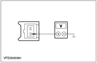
2 Measure voltage between fuse F23 (20 A) and "mass". |
|
|
• Is battery voltage being recorded? |
|
|
→ Yes |
|
|
Go to A3 |
|
|
→ No |
|
|
RESTORE power to fuse F23 using the wiring diagrams. CHECK the system is working properly. |
|
|
A3: FUSE CHECK F28 |
|
|
1 CHECK Fuse F28 (BJB). |
|
|
• Is the fuse good? |
|
|
→ Yes |
|
|
Go to A4 |
|
|
→ No |
|
|
REPLACE fuse F28 (10 A). CHECK the system is working properly. If the fuse blows again, LOCATE and REPAIR the short to ground using the wiring diagrams. |
|
|
A4: FUSE VOLTAGE CHECK F28 |
|
|
1 Connect Fuse F28 (BJB). |
|
|
2 Drive the ON position. |
|
|
3 Measure voltage between fuse F28 (10 A) and "mass". |
|
|
• Is battery voltage being recorded? |
|
|
→ Yes |
|
|
Go to A5 |
|
|
→ No |
|
|
RESTORE power to fuse F28 using the wiring diagrams. CHECK the system is working properly. |
|
|
A5: VOLTAGE CHECK IN AUXILIARY HEATER |
|
|
1 Enter the OFF position. |
|
|
2 Disconnect the C878 auxiliary heater. |
|
|
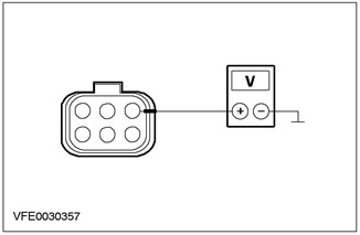
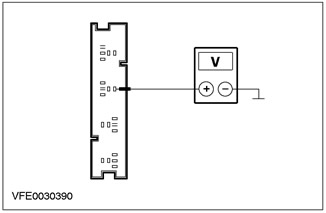
3 Measure the voltage between connector C878, pin 1, auxiliary heater circuit 30-RD18 (red), from the wiring harness side, and ground. |
|
• Is battery voltage being recorded? |
|
|
→ Yes |
|
|
Go to A6 |
|
|
→ No |
|
|
LOCATE and REPAIR the open circuit between the auxiliary heater and fuse F23 using the wiring diagrams. CHECK the system is working properly. |
|
|
A6: AUXILIARY HEATER VOLTAGE CHECK |
|
|
1 Drive the ON position. |
|
|
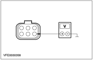
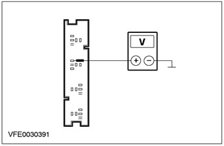
2 Measure the voltage between pin 4 of auxiliary heater connector C878, circuit 15-RD18 (green-red), from the wiring harness side, and ground. |
|
• Is battery voltage being recorded? |
|
|
→ Yes |
|
|
Go to A7 |
|
|
→ No |
|
|
LOCATE and REPAIR the open circuit between the auxiliary heater and S117 solder joint using the wiring diagrams. CHECK the system is working properly. |
|
|
A7: CHECK THE CONTROL VOLTAGE IN THE AUXILIARY HEATER |
|
|
NOTE: Use appropriate methods to cool down the outside temperature sensor to at least 5°C. |
|
|
1 Drive the START position. |
|
|
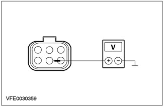
2 Measure the voltage between pin 5 of auxiliary heater connector C878, circuit 64S-RD18 (white-blue), from the wiring harness side, and ground. |
|
• Is battery voltage being recorded? |
|
|
→ Yes |
|
|
Go to A8 |
|
|
→ No |
|
|
Go to A9 |
|
|
A8: AUXILIARY HEATER GROUND CIRCUIT CHECK |
|
|
1 Enter the OFF position. |
|
|
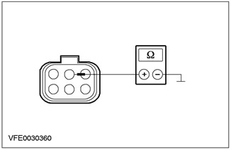
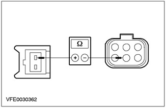
2 Measure the resistance between pin 2 of auxiliary heater connector C878, circuit 31-RD18 (black), from the wiring harness side, and ground. |
|
• Is the resistance less than 2 ohms? |
|
|
→ Yes |
|
|
CHECK and if necessary REPLACE the auxiliary heater. CHECK the system is working properly. |
|
|
→ No |
|
|
LOCATE and REPAIR the open circuit between the auxiliary heater and ground point G37 using the wiring diagrams. CHECK the system is working properly. |
|
|
A9: OUTDOOR TEMPERATURE SENSOR VOLTAGE CHECK |
|
|
1 Enter the OFF position. |
|
|
2 Disconnect the C875 outside temperature sensor. |
|
|
3 Drive the START position. |
|
|
4 Measure the voltage between pin 1 of connector C875, outdoor temperature sensor, circuit 64-RD18 (white-blue), from the wiring harness side, and ground. |
|
• Is battery voltage being recorded? |
|
|
→ Yes |
|
|
Go to A10 |
|
|
→ No |
|
|
Go to A11 |
|
|
A10: CHECK THE ELECTRICAL CIRCUIT BETWEEN THE OUTSIDE TEMPERATURE SENSOR AND THE AMPLIFIER HEATER FOR AN OPEN |
|
|
1 Enter the OFF position. |
|
|
2 Measure the resistance between pin 2 of connector C875, outdoor temperature sensor, circuit 64S-RD18 (white-blue), on the wiring harness side, and pin 5 of auxiliary heater connector 878, circuit 64S-RD18 (white-blue), from the wiring harness side. |
|
• Is the resistance less than 2 ohms? |
|
|
→ Yes |
|
|
REPLACE the outside temperature sensor. CHECK the system is working properly. |
|
|
→ No |
|
|
LOCATE and REPAIR open circuit 64S-RD18 (white-blue) between the outside temperature sensor and the booster heater using the wiring diagrams. CHECK the system is working properly. |
|
|
A11: VOLTAGE CHECK IN ENGINE RUN RELAY |
|
|
1 Enter the OFF position. |
|
|
2 Disconnect C1013 Engine Run Relay (BJB). |
|
|
3 Drive the ON position. |
|
|
4 Measure the voltage between pin 3 of connector C1013, engine run relay circuit 15-PA20 (green-orange), from the wiring harness side, and ground. |
|
• Is battery voltage being recorded? |
|
|
→ Yes |
|
|
Go to A12 |
|
|
→ No |
|
|
LOCATE and REPAIR open circuit 15-PA20 (green-orange) between the engine run relay and fuse F28, using the wiring diagrams. CHECK the system is working properly. |
|
|
A12: CHECK THE CONTROL VOLTAGE IN THE ENGINE RUN RELAY |
|
|
1 Measure the voltage between pin 1 of connector C1013 engine run relay circuit 15-PA19 (black and green), from the wiring harness side, and ground. |
|
• Is battery voltage being recorded? |
|
|
→ Yes |
|
|
Go to A13 |
|
|
→ No |
|
|
LOCATE and REPAIR the open circuit between the engine run relay and solder joint S117 using the wiring diagrams. CHECK the system is working properly. |
|
|
A13: CHECK ENGINE RUN RELAY GROUND ELECTRICAL CIRCUIT |
|
|
CAUTION: A test lamp rated at 12V and rated at 1.2W must be used when performing the following test. Otherwise, the PCM may be damaged or the test will give incorrect results. |
|
|
NOTE: Make sure the generator is working properly before taking the next measurement. |
|
|
1 Drive the START position. |
|
|
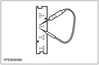
2 Use a test lamp to check the voltage between pins 1 and 2 of connector C1013 of the engine run relay (12 V, 1.2 W). |
|
• Is the indicator lamp on? |
|
|
→ Yes |
|
|
Go to A14 |
|
|
→ No |
|
|
Vehicles with 104-pin EEC: Go to A15 |
|
|
Vehicles with 121-pin EEC: Go to A16 |
|
|
A14: CHECK THE ELECTRICAL CIRCUIT BETWEEN ENGINE RUN RELAY AND OUTSIDE TEMPERATURE SENSOR FOR OPEN |
|
|
1 Enter the OFF position. |
|
|
2 Measure the resistance between pin 1 of connector C1013 engine run relay circuit 64-PA20 (yellow-blue), on the wiring harness side, and pin 1 C875 of the outdoor temperature sensor connector, circuit 64-RD18 (white-blue), from the wiring harness side. |
|
• Is the resistance less than 2 ohms? |
|
|
→ Yes |
|
|
REPLACE engine run relay. CHECK the system is working properly. |
|
|
→ No |
|
|
LOCATE and REPAIR the open circuit between the engine run relay and the outside temperature sensor using the wiring diagrams. CHECK the system is working properly. |
|
|
A15: CHECK THE ELECTRICAL CIRCUIT BETWEEN THE ENGINE RUN RELAY AND THE POWER PACK CONTROL MODULE (PCM) FOR A BREAK |
|
|
1 Enter the OFF position. |
|
|
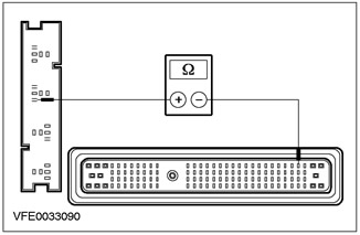
2 Disconnect the C415 PCM. |
|
|
3 Measure the resistance between C1013 Engine Run Relay Pin 2, harness side, and C415 PCM Pin 6, circuit 31S-PA19 (black and green), from the wiring harness side. |
|
• Is the resistance less than 2 ohms? |
|
|
→ Yes |
|
|
CHECK and REPLACE PCM if necessary. CHECK the system is working properly. |
|
|
→ No |
|
|
LOCATE and REPAIR the open circuit between the engine run relay and the PCM using the wiring diagrams. CHECK the system is working properly. |
|
|
A16: CHECK THE ELECTRICAL CIRCUIT BETWEEN THE ENGINE RUN RELAY AND THE POWER PACK CONTROL MODULE (PCM) FOR A BREAK |
|
|
1 Enter the OFF position. |
|
|
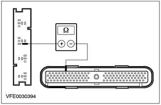
2 Disconnect the C414 PCM. |
|
|
3 Measure the resistance between C1013 engine run relay connector pin 2, harness side, and C414 PCM connector pin 23, circuit 31S-PA19 (black and green), from the wiring harness side. |
|
• Is the resistance less than 2 ohms? |
|
|
→ Yes |
|
|
CHECK and REPLACE PCM if necessary. CHECK the system is working properly. |
|
|
→ No |
|
|
LOCATE and REPAIR the open circuit between the engine run relay and the PCM using the wiring diagrams. CHECK the system is working properly. |
|
Pinpoint additional heating tests
PINPOINT TEST A: FUEL-FUELED AUXILIARY HEATER DOES NOT OPERATE
This article is available at russian, bulgarian, belarusian, ukrainian, serbian, croatian, romanian, polish, slovak, hungarian
« Previous articles
Diagnosis and checks of additional heating
Description and principle of operation of additional heating
Additional heating specifications
Heater housing — disassembly and assembly
Heater core — removal and installation
Heater and evaporator housing — removal and installation
Blower fan motor — removal and installation
Description and principle of operation
Torque specification
See other similar articles for Ford cars:
• Removal and installation of additional heating resistance Ford Mondeo 1 (1993-1996)
• Rear window heating switch Ford Escort 5 (1990-1997)
• Heating and ventilation Ford Fiesta 2 (1983-1989)
• Cooling, heating, air conditioning systems Ford Taurus 1 and 2 (1986-1994)
• Heating (air conditioning) and interior ventilation Ford Fusion (2002-2012)
Link to this page in different formats
HTMLTextBB Code
No comments yet
Focus 2
Focus Turnier 1
Focus 1
- General information
- Vehicle device
- Owner's manual
- Faults en route
- Maintenance
- First maintenance
- Second maintenance
- Applications
- Consumables and spare parts
- Auto mechanic tips
- Power unit
- Engine repair
- Engine seal parts
- Cooling system
- Exhaust system
- Supply system
- Clutch
- Car gearbox
- Front wheel drives
- Chassis
- Front suspension
- Rear suspension
- Steering
- Brake system
- Wheels and tires
- Body and coating
- Body elements
- Side doors
- Tailgate
- Salon elements
- Safety system
- Windshield wipers and washers
- Body Care
- Electrical equipment
- Instruments and motors
- Battery and alternator
- Egnition lock
- Engine management
- Headlights and lighting
- Switches and sensors
- Schematic diagrams
Focus Turnier 1
- General information
- Introduction to guide
- Car care
- Power unit
- Engine repair
- Lubrication system
- Cooling system
- Fuel injection (gasoline)
- Fuel injection (diesel)
- Ignition system
- Power and exhaust system
- Transmission
- Clutch and drive shafts
- Mechanical gearbox
- Automatic gearbox
- Chassis
- Car suspension
- Steering
- Wheels and tires
- Brake system
- Body
- Exterior
- Interior
- Heating and ventilation
- Electrical equipment
- Equipment and devices
- Lighting and signaling
- Power devices
- Electrical circuits
Focus 1
- General information
- Using the manual
- Identification codes
- Power unit
- Engine
- Engine 1.4/1.6 Zetec-SE
- Engine 1.6/1.8/2.0 Zetec-E
- Engine Duratec ST 2.0 l
- Engine Duratec 8V 1.6 l
- Diesel engine 1.8 l
- Engine cooling
- Fuel supply
- Accessory drive
- Launch system
- Ignition system
- Air and vapor
- Engine management
- Exhaust toxicity
- Exhaust system
- Automatic gearbox
- Clutch
- Mechanical gearbox iB5
- Mechanical gearbox MTX-75
- Mechanical gearbox MT285
- Chassis
- Front suspension
- Rear suspension
- Wheels and tires
- Front axle axles
- Brake system
- Hydraulic brake
- Anti-lock braking system
- Steering
- Body and coating
- Body panels
- Body elements
- Salon elements
- Glass, frames and mechanisms
- Windshield wipers and washers
- Car sunroof
- Seat belts
- Body repairs
- Back elements
- Electrical equipment
- Climate control
- Heating and ventilation
- Instruments and control lamps
- Battery and alternator
- Audio system
- Headlights and lighting
- Power distribution
- Electronic Function Group
FordBook.ru © 2014-2024 • Mobile version • Interesting to read • Sitemap: EN BG BY UA RS HR RO PL SK HU • Site search • Contact with administration
Focus 1 • Focus Turnier 1 • Focus 2 • Mondeo 1 • Mondeo 1 and 2 • Mondeo 2 • Mondeo 3 • Mondeo 4 • Escort 3 • Escort 4 • Escort 5 • Fiesta 2 • Fiesta 4 • Taurus 1 and 2 • Fusion • Scorpio 1 • Scorpio 2 • Sierra •
Focus 1 • Focus Turnier 1 • Focus 2 • Mondeo 1 • Mondeo 1 and 2 • Mondeo 2 • Mondeo 3 • Mondeo 4 • Escort 3 • Escort 4 • Escort 5 • Fiesta 2 • Fiesta 4 • Taurus 1 and 2 • Fusion • Scorpio 1 • Scorpio 2 • Sierra •
Visitor comments