|
STATES |
DETAILS/RESULTS/ACTIONS |
|
NOTE:The additional electric heater with coolant heating only operates when the engine is running (D+ signal from the alternator) and provided that the alternator efficiency is adequate. The coolant temperature must not exceed 75°C and the outside temperature must be below 5°C. |
|
|
B1: DETERMINING THE CONDITIONS UNDER WHICH A FAILURE OCCURRES |
|
|
1Check the operation of the additional electric heater with coolant heating. |
|
|
• Levels 1 and 2 of the auxiliary heater with coolant heating do not work? |
|
|
→ Yes |
|
|
Go to B2 |
|
|
→ No |
|
|
Only level 1 doesn't work: Go to B5 |
|
|
Only level 2 doesn't work: Go to B14 |
|
|
B2: CHECKING CONTROL VOLTAGE IN THE AUXILIARY HEATER GLOW PLUG RELAY, LEVEL 1 |
|
|
1Enter the OFF position. |
|
|
2Disconnect C1002 auxiliary heater glow plug relay, level 1 (BJB). |
|
|
3Enter the ON position. |
|

|
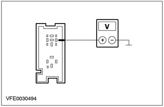
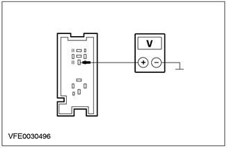
4Measure the voltage between pin 1 of the auxiliary heater glow plug relay connector C1002, level 1, circuit 15-RH23 (GN/RD), wiring harness side and ground. |
|
• Is battery voltage registered? |
|
|
→ Yes |
|
|
Go to B3 |
|
|
→ No |
|
|
LOCATE and REPAIR the open in the 15-RH10 (Green/Red) circuit between the power hold relay and solder joint S117 using the wiring diagrams. CHECK for proper system operation. |
|
|
B3: CHECKING THE SIGNAL FROM THE AIR INTAKE TEMPERATURE SENSOR |
|
|
NOTE:The air intake temperature sensor is built into the mass air flow sensor. |
|
|
1Enter the OFF position. |
|
|
2Connect the diagnostic tool. |
|
|
3Enter the ON position. |
|
|
4Check the air intake temperature signal using WDS. |
|
|
• Is the air intake temperature signal OK, i.e. the indicated temperature value is probable? |
|
|
→ Yes |
|
|
Go to B4 |
|
|
→ No |
|
|
For more information, refer to For more information, refer to Section 303-14. |
|
|
B4: CHECKING THE GROUND CIRCUIT OF THE AUXILIARY ELECTRIC HEATER WITH COOLANT HEATING |
|
|
1Enter the OFF position. |
|
|
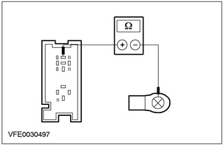
2Measure the resistance between the auxiliary electric coolant heater connector C965, circuit 15-RD22 (green/red), and ground. |
|
• Resistance less than 1.1 ohms? |
|
|
→ Yes |
|
|
CHECK the powertrain control module (PCM) and REPLACE it if necessary. CHECK the system for proper operation. |
|
|
→ No |
|
|
CHECK the auxiliary electric coolant heater ground circuit, CLEAN the bulkhead thread(s) if necessary. CHECK the system for proper operation. |
|
|
B5: CHECKING FUSE F24 |
|
|
1Enter the OFF position. |
|
|
2CHECK Fuse F24 (BJB). |
|
|
• Is the fuse good? |
|
|
→ Yes |
|
|
Go to B6 |
|
|
→ No |
|
|
REPLACE fuse F24 (30A). CHECK the system for proper operation. If the fuse blows again, LOCATE and REPAIR the short to ground using the wiring diagrams. |
|
|
B6: CHECKING THE VOLTAGE IN FUSE F24 |
|
|
1Connect Fuse F24 (BJB). |
|
|
2Check the voltage in the electrical circuit between fuse F24 (30 A) and ground. |
|
|
• Is battery voltage registered? |
|
|
→ Yes |
|
|
Go to B7 |
|
|
→ No |
|
|
RESTORE power to fuse F24 using the wiring diagrams. CHECK that the system is operating correctly. |
|
|
B7: CHECKING CONTROL VOLTAGE IN THE AUXILIARY HEATER GLOW PLUG RELAY, LEVEL 1 |
|
|
1Disconnect C1002 auxiliary heater glow plug relay, level 1 (BJB). |
|
|
2Enter the ON position. |
|

|
3Measure the voltage between pin 1 of the auxiliary heater glow plug relay connector C1002, level 1, circuit 15-RH23 (GN/RD), wiring harness side and ground. |
|
• Is battery voltage registered? |
|
|
→ Yes |
|
|
Go to B8 |
|
|
→ No |
|
|
LOCATE and REPAIR the open in circuit 15-RH23 (Green/Red) between the Aux Heater Glow Plug Relay, Stage 1 and solder joint S117 using the Wiring Diagrams. CHECK for proper system operation. |
|
|
B8: CHECKING THE VOLTAGE IN THE AUXILIARY HEATER GLOW PLUG RELAY, LEVEL 1 |
|
|
1Enter the OFF position. |
|

|
2Measure the voltage between pin 3 of connector C1002 auxiliary heater glow plug relay, level 1, circuit 30-RH24 (red), wiring harness side and ground. |
|
• Is battery voltage registered? |
|
|
→ Yes |
|
|
Go to B9 |
|
|
→ No |
|
|
LOCATE and REPAIR the open in circuit 30-RH24 (red) between the booster heater glow plug relay, stage 1, and fuse F24 using the Wiring Diagrams. CHECK for proper system operation. |
|
|
B9: CHECK THE ELECTRICAL CIRCUIT BETWEEN THE AUXILIARY HEATER GLOW PLUG RELAY LEVEL 1 AND THE AUXILIARY ELECTRIC HEATER WITH COOLANT HEATER FOR OPEN CIRCUIT. |
|

|
1Measure the resistance between glow plug relay connector C1002 pin 5, level 1, harness side and auxiliary electric heater with coolant heater connector C965, circuit 15-RD22 (green/red). |
|
• Resistance less than 0.5 Ohm? |
|
|
→ Yes |
|
|
Go to B10 |
|
|
→ No |
|
|
LOCATE and REPAIR the open in the electrical circuit between the Aux Heater Glow Plug Relay, Level 1 and the Electric Aux Heater with Coolant Heater using the Wiring Diagrams. CHECK for proper system operation. |
|
|
B10: CHECKING THE ADDITIONAL HEATER WITH COOLANT HEATING |
|

|
1Measure the resistance between the auxiliary heater with coolant heater connector C965, circuit 15-RD22 (green/red), and ground. |
|
• Resistance less than 1.1 ohms? |
|
|
→ Yes |
|
|
Go to B11 |
|
|
→ No |
|
|
REPLACE the auxiliary heater with coolant heating. CHECK the system for proper operation. |
|
|
B11: CHECKING THE AUXILIARY HEATER GLOW PLUG RELAY, LEVEL 1 |
|
|
1Check the auxiliary heater glow plug relay, level 1, in accordance with the component tests described at the end of this section. |
|
|
• Aux Heater Glow Plug Relay Level 1 OK? |
|
|
→ Yes |
|
|
Vehicles with 104-pin EEC: Go to B12 |
|
|
Vehicles with 121-pin EEC: Go to B13 |
|
|
→ No |
|
|
REPLACE the auxiliary heater glow plug relay, level 1. CHECK the system for proper operation. |
|
|
B12: CHECK CIRCUIT BETWEEN PCM AND AUXILIARY HEATER GLOW PLUG RELAY, LEVEL 1 FOR OPEN |
|
|
1Disconnect C415 PCM. |
|
|
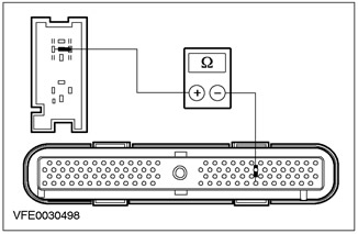
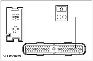
2Measure the resistance between pin 2 of the auxiliary heater glow plug relay, level 1, connector C1002, harness side and pin 98 of the PCM connector C415, circuit 31S-RH23 (BK/OG), harness side. |
|
• Resistance less than 2 ohms? |
|
|
→ Yes |
|
|
CHECK the PCM and REPLACE it if necessary. CHECK the system is operating correctly. |
|
|
→ No |
|
|
LOCATE and REPAIR the open in the circuit between the PCM and the Supplemental Heater Glow Plug Relay, Level 1 using the Wiring Diagrams. CHECK for proper system operation. |
|
|
B13: CHECK CIRCUIT BETWEEN PCM AND AUXILIARY HEATER GLOW PLUG RELAY, LEVEL 1 FOR OPEN |
|
|
1Disconnect C414 PCM. |
|
|
2Measure the resistance between pin 1 of connector C1002 of the glow plug relay, level 2, wiring harness side and pin 61 of connector C414 of the PCM, circuit 31S-RH23 (BK/OG), wiring harness side. |
|
• Resistance less than 2 ohms? |
|
|
→ Yes |
|
|
CHECK the PCM and REPLACE it if necessary. CHECK the system is operating correctly. |
|
|
→ No |
|
|
LOCATE and REPAIR the open in the circuit between the PCM and the Supplemental Heater Glow Plug Relay, Level 1 using the Wiring Diagrams. CHECK for proper system operation. |
|
|
B14: CHECKING FUSE F3 |
|
|
1Enter the OFF position. |
|
|
2CHECK Fuse F3 (BJB). |
|
|
• Is the fuse good? |
|
|
→ Yes |
|
|
Go to B15 |
|
|
→ No |
|
|
REPLACE fuse F3 (40A). CHECK the system for proper operation. If the fuse blows again, LOCATE and REPAIR the short to ground using the wiring diagrams. |
|
|
B15: CHECKING THE VOLTAGE IN FUSE F3 |
|
|
1Connect Fuse F3 (BJB). |
|
|
2Check the voltage in the electrical circuit between fuse F3 (40 A) and ground. |
|
|
• Is battery voltage registered? |
|
|
→ Yes |
|
|
Go to B16 |
|
|
→ No |
|
|
RESTORE power to fuse F3 using the wiring diagrams. CHECK that the system is operating correctly. |
|
|
B16: CHECKING CONTROL VOLTAGE IN THE AUXILIARY HEATER GLOW PLUG RELAY, LEVEL 2 |
|
|
1Disconnect C1010 auxiliary heater glow plug relay, level 2 (BJB). |
|
|
2Enter the ON position. |
|
|
3Measure the voltage between pin 1 of the auxiliary heater glow plug relay connector C1010, level 2, circuit 15-RH25 (GRN/BK), wiring harness side and ground. |
|
• Is battery voltage registered? |
|
|
→ Yes |
|
|
Go to B17 |
|
|
→ No |
|
|
LOCATE and REPAIR the open in circuit 15-RH25 (BK/GN) between the auxiliary heater glow plug relay, stage 2 and solder joint S117 using the Wiring Diagrams. CHECK for proper system operation. |
|
|
B17: CHECKING THE VOLTAGE IN THE AUXILIARY HEATER GLOW PLUG RELAY, LEVEL 2 |
|
|
1Enter the OFF position. |
|
|
2Measure the voltage between pin 3 of the auxiliary heater glow plug relay connector C1010, level 2, circuit 30-RH26 (red), wiring harness side and ground. |
|
• Is battery voltage registered? |
|
|
→ Yes |
|
|
Go to B18 |
|
|
→ No |
|
|
LOCATE and REPAIR the open in circuit 30-RH26 (Red) between the Aux Heater Glow Plug Relay, Stage 2 and fuse F3 using the Wiring Diagrams. CHECK for proper system operation. |
|
|
B18: CHECK FOR OPEN CIRCUIT BETWEEN AUXILIARY HEATER GLOW PLUG RELAY LEVEL 2 AND AUXILIARY ELECTRIC HEATER WITH COOLANT HEATER. |
|
|
1Measure the resistance between pin 5 of connector C1010 of the glow plug relay of the auxiliary heater, level 2, wiring harness side, and connector C967 of the electric auxiliary heater with coolant heater, wiring harness side. |
|
• Resistance less than 0.5 Ohm? |
|
|
→ Yes |
|
|
Go to B19 |
|
|
→ No |
|
|
LOCATE and REPAIR the open in the electrical circuit between the Aux Heater Glow Plug Relay Level 2 and the Electric Aux Heater with Coolant Heater using the Wiring Diagrams. CHECK for proper system operation. |
|
|
B19: CHECKING THE ADDITIONAL HEATER WITH COOLANT HEATING |
|

|
1Measure the resistance between the auxiliary heater with coolant heater connector C966, circuit 15-RD23 (black/green), and ground. |
|
• Resistance less than 0.8 ohms? |
|
|
→ Yes |
|
|
Go to B20 |
|
|
→ No |
|
|
REPLACE the auxiliary heater with coolant heating. CHECK the system for proper operation. |
|
|
B20: CHECKING THE AUXILIARY HEATER GLOW PLUG RELAY, LEVEL 2 |
|
|
1Check the auxiliary heater glow plug relay, level 2, in accordance with the component tests described at the end of this section. |
|
|
• Auxiliary Heater Glow Plug Relay Level 2 OK? |
|
|
→ Yes |
|
|
Vehicles with 104-pin EEC: Go to B21 |
|
|
Vehicles with 121-pin EEC: Go to B22 |
|
|
→ No |
|
|
REPLACE the auxiliary heater glow plug relay, level 2. CHECK the system for proper operation. |
|
|
B21: CHECK CIRCUIT BETWEEN PCM AND AUXILIARY HEATER GLOW PLUG RELAY, LEVELS 2 FOR OPEN |
|
|
1Disconnect C415 PCM. |
|
|
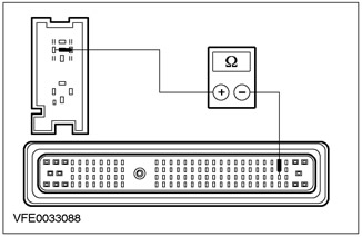
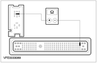
2Measure the resistance between pin 2 of connector C1010, auxiliary heater glow plug relay, level 2, wiring harness side and pin 75 of connector C415, circuit 31S-RH25 (black/green), wiring harness side. |
|
• Resistance less than 2 ohms? |
|
|
→ Yes |
|
|
CHECK the PCM and REPLACE it if necessary. CHECK the system is operating correctly. |
|
|
→ No |
|
|
LOCATE and REPAIR the open in the circuit between the PCM and the Supplemental Heater Glow Plug Relay, Level 2 using the Wiring Diagrams. CHECK for proper system operation. |
|
|
B22: CHECK CIRCUIT BETWEEN PCM AND AUXILIARY HEATER GLOW PLUG RELAY, LEVELS 2 FOR OPEN |
|
|
1Disconnect C414 PCM. |
|
|
2Measure the resistance between pin 2 of connector C1010, glow plug relay, level 2, wiring harness side and pin 62 of connector C414, circuit 31S-RH25 (black/green), wiring harness side. |
|
• Resistance less than 2 ohms? |
|
|
→ Yes |
|
|
CHECK the PCM and REPLACE it if necessary. CHECK the system is operating correctly. |
|
|
→ No |
|
|
LOCATE and REPAIR the open in the circuit between the PCM and the Supplemental Heater Glow Plug Relay, Level 2 using the Wiring Diagrams. CHECK for proper system operation. |
|
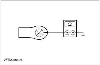
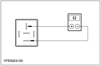
Element checks
Additional heater glow plug relay
1. Check the normally open contact in the non-switching state.
- Measure the resistance between pins 3 and 5 of the relay, on the element side.
- Is the resistance registered to be greater than 10 kOhm? If yes, go to step 2. If no, replace the relay.
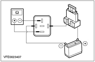
2. Check the normally open contact in the switching state.
- Using a 1 Amp fused test lead, connect relay pin 1, cell side, to the positive battery terminal.
- Using a test lead, connect pin 2 of the relay, on the cell side, to the negative terminal of the battery.
- Measure the resistance between pins 3 and 5 of the relay, on the element side.
- Is the resistance less than 2 ohms? If yes, the relay is OK. If not, REPLACE the relay.
(The original source of the publication is on the website: fordbook)