Contents: Additional heater in section ↳ Expanded image - additional heater ↳ Electric additional heater… ↳
Diesel vehicles intended for the Scandinavian market are equipped with a fuel-fired auxiliary heater because the low outside temperature and high engine efficiency mean that the engine does not produce enough heat to provide effective heating.
As a result, the auxiliary heater increases the coolant temperature to ensure sufficient heating of the air passing through the heat exchanger.
The maximum power of the additional heater is 5 kW, and the minimum is 2.2 kW.
The fuel pump, connected to the auxiliary heater, supplies diesel fuel from the fuel supply line to the pre-chamber.
An additional pressure control valve is installed before the fuel pump to reduce the fuel pressure to below 0.2 bar.
The exhaust gases are discharged to the outside through a separate exhaust system.
The smoke that appears when the additional heater is first turned on is normal and is a consequence of the nature of the combustion process.
The additional heater is automatically activated after the engine is started (D+ signal from the generator is activated) if the outside temperature is below 5°C and the coolant temperature is below 75°C. The coolant temperature is controlled by the system whenever the vehicle is running.
The system will not be automatically activated if the coolant temperature reaches 85°C or if it is not functioning properly.
The system turns off under the following conditions:
- if after the second attempt to start the ignition does not occur (after a pause of 90 seconds)
- if the flame goes out during operation and the second attempt to start the heater is unsuccessful
- if overheating causes the overheating sensor to be triggered
- if the voltage exceeds/falls below the specified value, or if the power supply to the glow plug or metering pump is interrupted
- if the fan wheel is blocked or faulty.
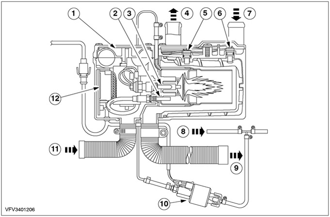
Additional heater in section
| Pos. | Spare Part No | Name |
| 1 | - | Combustion chamber air supply fan |
| 2 | - | Flame sensor |
| 3 | - | Glow plug |
| 4 | - | Coolant release |
| 5 | - | Temperature sensor |
| 6 | - | Overheating sensor |
| 7 | - | Coolant inlet |
| 8 | - | Fuel line |
| 9 | - | Exhaust gases |
| 10 | - | Fuel injection pump |
| 11 | - | Fresh air intake |
| 12 | - | Electronic control unit |
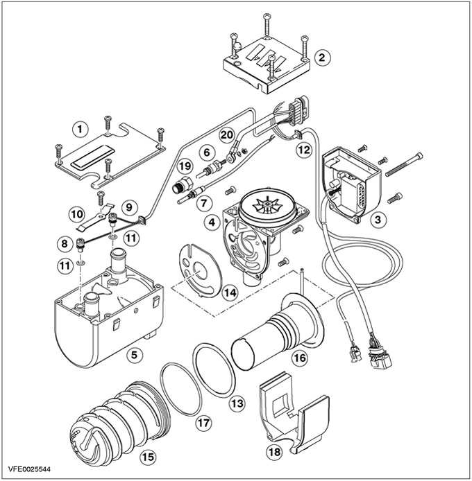
Expanded image - additional heater
| Pos. | Spare Part No | Name |
| 1 | - | Cooling bushing cover |
| 2 | - | Combustion air supply fan cover |
| 3 | - | Electronic control unit |
| 4 | - | Combustion chamber air supply fan |
| 5 | - | Cooling bushing |
| 6 | - | Glow plug |
| 7 | - | Flame sensor |
| 8 | - | Overheating sensor |
| 9 | - | Temperature sensor |
| 10 | - | Compression spring |
| 11 | - | O-ring |
| 12 | - | Wiring harness |
| 13 | - | Pad |
| 14 | - | Pad |
| 15 | - | Heat exchanger |
| 16 | - | Combustion chamber |
| 17 | - | O-ring |
| 18 | - | Fan Motor Cover |
| 19 | - | Adapter |
| 20 | - | Glow Plug Wiring Harness |
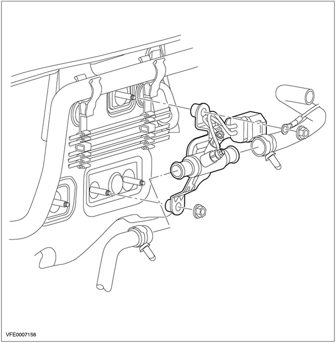
Electric additional heater (automatic)
Vehicles with diesel engines intended for the European market (excluding Scandinavia) will be equipped with an electrically powered additional heater.
Additional heater settings with three glow plugs (0; 1; 2; 3) are controlled by the powertrain control module (PCM) and switched by two relays. The PCM control ensures that the battery is kept at a sufficient charge level. The auxiliary heater is switched off when the demand for electricity for all the switched-on loads causes the battery charge level to drop. To control the auxiliary heaters, the PCM evaluates the following signals:
- cylinder head temperature,
- air intake temperature,
- generator Charge State (ALFF).
CAUTION: Glow plugs are not replaceable. Threaded connection has a single-use seal. Auxiliary heater must be replaced as an assembly.