


Contents: Main parameters ↳ Cylinder head ↳ Engine cylinder block ↳ Crank mechanism ↳ Gas distribution system ↳
Engines - gasoline, four-stroke, four-cylinder, in-line, water-cooled, have a camshaft in the cylinder head, installed transversely in front of the car.
Main parameters
Engine | 1,3 HC OHC | 1.6 NS ONS | 1.6 NS ONS economical | 2.0 NS ONS |
| Engine type | JCT | LCT | LCS | NET |
| Cylinder diameter (mm) | 79,02 | 87,67 | 87,67 | 90,82 |
| Piston stroke (mm) | 66,00 | 66,00 | 66,00 | 76,95 |
| Volume (cm³) | 1294 | 1593 | 1593 | 1993 |
| Compression ratio | 9,0 | 9,2 | 9,2 | 9,2 |
| Compression pressure (MPa) | 1,1 – 1,3 | 1,1 – 1,3 | 1,1 – 1,3 | 1,1 – 1,3 |
| Nominal power: | ||||
| – kW at rpm | 44 at 5700 | 55 at 5300 | 55 at 5700 | 77 at 5200 |
| – HP at rpm | 60 at 5700 | 75 at 5600 | 75 at 5700 | 105 at 5200 |
| Maximum torque (Nm at rpm) | 98 at 3100 | 120 at 2900 | 120 at 2900 | 157 at 4000 |
Cylinder head
The head is made of a special alloy and has valve seats made directly in the cylinder head material.
| Designation: | |
| – 1.3 dm³ engine | 3 |
| – 1.6 dm³ engine | 6 |
| – 2.0 dm³ engine | 0 |
| Valve seating angle | 44°30' – 45° |
| Valve seat contact width: | |
| - intake | 1.5 mm |
| - graduation | 2.0 mm |
| Maximum depth of regrinding of the lower plane of the cylinder head | 0.154 mm |
| Diameters of the holes of the camshaft bearing seats: | |
| - front bearing | 45.072 – 45.102 mm |
| - middle bearing | 47.692 – 47.772 mm |
| - rear bearing | 48.072 – 48.102 mm |
Cylinder head gasket
Brand: Reinz.
Valve guides
The guide holes are made directly in the cylinder head.
| Nominal diameter | 8.063 – 8.088 mm |
| Repair size: | |
| - excess of 0.2 | 8.263 – 8.288 mm |
| - excess of 0.4 | 8.463 – 8.488 mm |
Valves
The valves are installed in the cylinder head and are inclined at an angle of 7°30' to the cylinder axis.
Valve dimensions (mm)
| Engine | 1.3 dm³ | 1.6 dm³ | 2.0 dm³ |
| Inlet valve: | |||
| - length | 112,65 – 113,65 | 112,65 – 113,65 | 110,65 – 111,65 |
| – plate diameter | 38,30 – 38,70 | 41,80 – 42,20 | 41,80 – 42,20 |
| Exhaust valve: | |||
| - length | 112,05 – 113,75 | 112,05 – 113,75 | 110,10 – 112,05 |
| – plate diameter | 29,80 – 30,20 | 34,00 – 34,40 | 35,80 – 36,20 |
The dimensions of the intake valves are common to all engines.
Rod diameter
| Nominal | 8.025 – 8.043 mm |
| Repair size +0.2 | 8.225 – 8.243 mm |
| Repair size +0.4 | 8.425 – 8.443 mm |
| Repair size +0.6 | 8.625 – 8.643 mm |
| Repair size +0.8 | 8.825 – 8.843 mm |
The dimensions of the exhaust valves are common to all engines.
Rod diameter
| Nominal | 7.999 – 8.017 mm |
| Repair size +0.2 | 8.199 – 8.217 mm |
| Repair size +0.4 | 8.399 – 8.417 mm |
| Repair size +0.6 | 8.599 – 8.617 mm |
| Repair size +0.8 | 8.799 – 8.817 mm |
The clearance of the rod in the guide is 0.046–0.089 mm.
| Valve clearance (cold engine): | |
| - inlet valve | 0.20 mm |
| - exhaust valve | 0.25 mm |
Valve springs
The same springs are used for the intake and exhaust valves.
| Spring diameter | 23.445 – 23.95 mm |
| Spring wire diameter | 3.87 – 3.93 mm |
| Number of turns | 4,7 |
| Free length | 47.00 mm |
Engine cylinder block
The engine cylinder block is cast from cast iron. The cylinders are made directly in the cylinder block.
| Bearing support width | 27.17 – 27.22 mm |
| Inner diameters of main bearings (measured vertically): | |
| - nominal | 57,000 – 57,034 mm |
| – repair size -0.25 | 56.750 – 56.784 mm |
| – repair size -0.50 | 56,500 – 56,534 mm |
| – repair size -0.75 | 56.250 – 56.284 mm |
| – repair size -1.00 | 56,000 – 56,034 mm |
| Diameters of the holes of the main bearing seats in the cylinder block: | |
| – nominal size | 60.620 – 60.640 mm |
| – repair size +0.4 | 61,020 – 61,040 mm |
Cylinder diameters (mm)
| Engine | 1.3 dm³ | 1.6 dm³ | 2.0 dm³ |
| Designation | 13 | 16 | 20 |
| Nominal standard diameters: | |||
| - group 1 | 79,000 – 79,010 | 87,650 – 87,660 | 90,800 – 90,810 |
| - group 2 | 79,010 – 79,020 | 87,660 – 87,670 | 90,810 – 90,820 |
| - group 3 | 79,020 – 79,030 | 87,670 – 87,680 | 90,820 – 90,830 |
| - group 4 | 79,030 – 79,040 | 87,680 – 87,690 | 90,830 – 90,840 |
| Nominal diameters with tolerance: | |||
| - Group A | 79,510 – 79,520 | 88,160 – 88,170 | 91,310 – 91,320 |
| - Group B | 79,520 – 79,530 | 88,170 – 88,180 | 91,320 – 91,330 |
| - Group C | 79,530 – 79,540 | 88,180 – 88,190 | 91,330 – 91,340 |
| Repair size diameters: | |||
| - standard | 79,030 – 79,040 | 87,680 – 87,690 | 90,830 – 90,840 |
| – with a tolerance of 0.5 | 79,530 – 79,540 | 88,180 – 88,190 | 91,330 – 91,340 |
| – with a tolerance of 1.0 | 80,030 – 80,040 | 88,680 – 88,690 | 91,830 – 91,840 |
Crank mechanism
Crankshaft
The steel crankshaft is supported by five bearings.
| Axial play | 0.08 – 0.28 mm |
| Main journal diameters: | |
| – nominal size | 56,970 – 56,990 mm |
| – repair size -0.25 | 56,720 – 56,740 mm |
| – repair size -0.50 | 56,470 – 56,490 mm |
| – repair size -0.75 | 56.220 – 56.240 mm |
| – repair size -1.00 | 55.970 – 55.990 mm |
| Main bearing clearance | 0.010 – 0.064 mm |
| Measurements are taken using Plastigage measuring rods. | |
| Connecting rod journal diameters: | |
| – nominal size | 51,980 – 52,000 mm |
| – repair size -0.25 | 51,730 – 51,750 mm |
| – repair size -0.50 | 51,480 – 51,500 mm |
| – repair size -0.75 | 51.230 – 51.250 mm |
| Thickness of thrust half rings: | |
| – nominal size | 2.30 – 2.35 mm |
| - repair size | 2.50 – 2.55 mm |
Flywheel
The flywheel is secured to the crankshaft flange with six bolts.
Intermediate shaft
The intermediate shaft is located in the front part of the cylinder block, on the left side. Provides drive for the ignition distributor, as well as the oil and fuel pumps.
Axial clearance: 0.050–0.204 mm.
Connecting rods
The connecting rods are forged from steel and have an I-beam profile in their cross-section. The piston pin is pressed into the connecting rod head.
| Connecting rod head bore diameter | 23.964 – 23.976 mm |
| Connecting rod pin tension: | 0.018 – 0.039 mm |
| Connecting rod head heating temperature during pin installation | 250 – 300°C |
| Connecting rod base bore diameter | 55,000 – 55,020 mm |
| Inner diameters of connecting rod bearing holes: | |
| – nominal size | 52.006 – 52.044 mm |
| – repair size -0.25 | 51.756 – 51.794 mm |
| – repair size -0.50 | 51.706 – 51.744 mm |
| – repair size -0.75 | 51.256 – 56.294 mm |
| – repair size -1.00 | 51.006 – 51.044 mm |
| Main bearing clearance | 0.006 – 0.064 mm |
Measurements are taken using Plastigage measuring rods. | |
| Permissible non-perpendicularity of the hole axis relative to the connecting rod axis: | |
| - head hole | 0.10 mm |
| - base hole | 0.15 mm |
Pistons
The pistons are made of light alloy, without grooves on the conductive part, with a cast invar ring, limiting thermal errors in dimensions. In the upper part there are three grooves for piston rings. The axis of the piston pin hole is offset relative to the piston axis. Pistons are supplied in sets together with pins and connecting rods.
Installation method: The arrow on the bottom of the piston should point towards the front of the engine (towards the timing drive).
Piston pins
The pins, made of a steel alloy and subjected to heat treatment, are pressed into the connecting rod heads (hot installation at a head temperature of 250°–300°C) and rotate in the piston hubs.
| Length: | |
| – 1.3 dm³ engine | 60.0 – 60.8 mm |
| – 1.6 dm³ engine | 68.0 – 68.8 mm |
| – engine 2.0 dm³ | 72.0 – 72.8 mm |
| Diameter: | |
| - marked in red | 23,994 – 23,997 |
| - marked in blue | 23,997 – 24,000 |
| - marked in red | 22,000 – 24,003 |
| Piston hub clearance | 0.008 – 0.014 mm |
| Connecting rod head tension | 0.018 – 0.039 mm |
Piston dimensions (mm)
Engine | 1.3 dm³ | 1.6 dm³ | 2.0 dm³ |
| Nominal standard diameters: | |||
| - group 1 | 78,965 – 78,975 | 87,615 – 87,625 | 90,765 – 90,775 |
| - group 2 | 78,975 – 78,985 | 87,625 – 87635 | 90,775 – 90,785 |
| - group 3 | 78,985 – 78,995 | 87,635 – 87,645 | 90,785 – 90,795 |
| - group 4 | 78,995 – 79,005 | 87,645 – 87,655 | 90,795 – 90,805 |
| Repair size diameters: | |||
| - standard | 78,900 – 79,015 | 87,640 – 87,665 | 90,780 – 90,805 |
| – with a tolerance of 0.5 | 79,490 – 79,515 | 88,140 – 88,165 | 91,280 – 91,305 |
| – with a tolerance of 1.0 | 79,990 – 80,015 | 88,640 – 88,665 | 91,780 – 91,805 |
| Clearance of new pistons in cylinders | 0,015 – 0,050 | 0,015 – 0,050 | 0,025 – 0,060 |
Piston rings
Each piston has three rings: two sealing rings and one oil scraper ring.
| Clearance of the sealing ring lock (located in the cylinder): | |
| – engine 1.3 dm³ and engine 1.6 dm³ | 0.30 – 0.50 mm |
| – engine 2.0 dm³ | 0.038 – 0.048 mm |
| Oil scraper ring lock clearance | 0.40 – 1.40 mm |
Location of ring locks:
- sealing - 150° (in opposite directions) relative to the oil scraper ring lock;
- oil scraper - the expansion spring lock is installed in accordance with the direction of the arrow on the bottom of the piston; the locks of the upper and lower plates are installed 25 mm to the right and left of the direction of the arrow.
Gas distribution system
Four-cylinder in-line engine OHC (general view)
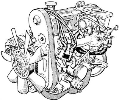
The camshaft is located in the cylinder head, drives the valves via a valve lever and is driven by a toothed belt.
Valve clearance (cold):
- inlet: 0.20 mm;
- outlet: 0.25 mm.
Distribution phases
| Engine | 1.3 dm³ and 1.6 dm³ | 2.0 dm³ |
| OZD | 22° before TDC | 24° before TDC |
| ZZD | 54° after BDC | 64° after BDC |
| OZW | 64° before BDC | 70° before BDC |
| ZZW | 12° after TDC | 18° after TDC |
OZD and ZZD – opening and closing of the intake valve, respectively;
OZW and ZZW – opening and closing of the exhaust valve, respectively;
TDC and BDC are top and bottom dead centers, respectively.
Toothed belt
| Brand: Ford Powergrip | Type: |
| – 1.3 dm³ engine | 70NM 6288 AA |
| – 1.6 dm³ engine | 70NM 6288 AA |
| – 2.0 dm³ engine | 70NM 6268 AA |
| Number of teeth | |
| – 1.3 dm³ engine | 119 |
| – engine 1.6 dm³ | 119 |
| – 2.0 dm³ engine | 122 |
Camshaft
The camshaft rotates in three bearings.
| Camshaft bearing diameters: | |
| - front | 41.987 – 42.013 mm |
| - average | 44.607 – 44.633 mm |
| - rear | 44.987 – 45.013 mm |
| Inner diameters of bearing bushings: | |
| - front | 42.035 – 42.055 mm |
| - average | 44.655 – 44.675 mm |
| - rear | 45.035 – 45.055 mm |
| Camshaft axial play | 0.104 – 0.204 mm |
| Thickness of camshaft thrust washers | 3.96 – 4.01 mm |
| Cam lift: | |
| – 1.3 dm³ engine | 5.9639 mm |
| – 1.6 dm³ engine | 5.9639 mm |
| – 2.0 dm³ engine | 6.3323 mm |
| Height of cams: | – 1.3 dm³ engine | 35.894 – 36.234 mm | – engine 1.6 dm³ | 35.894 – 36.234 mm |
| – 2.0 dm³ engine | 36,260 – 36,600 mm |