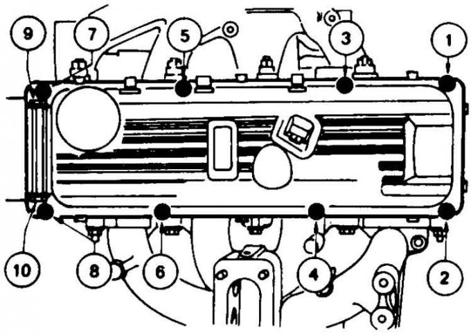
Cylinder Head Cover Bolt Tightening Sequence
Checking valve clearances
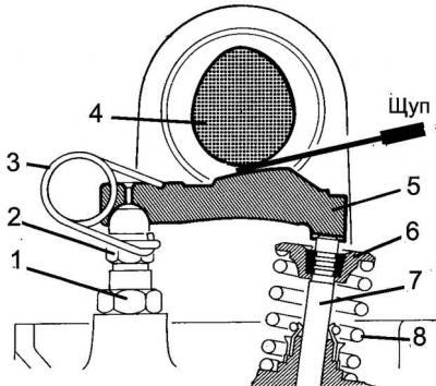
1 – lock nut, 2 – adjusting bolt, 3 – spring, 4 – cam, 5 – pusher (lever), 6 – plate, 7 – valve, 8 – valve spring
Adjusting valve clearances
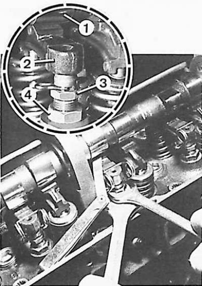
1 – cam, 2 – pusher (valve lever), 3 – adjusting bolt, 4 – lock nut
1. Remove the air filter and disconnect the high tension wires from the ignition distributor and spark plugs.
2. Remove the cylinder head cover by unscrewing the ten bolts that secure it (in the reverse order to that shown (see Fig. Cylinder head cover bolt tightening order).
3. Remove the spark plugs to make it easier to turn the engine crankshaft.
4. Turn the crankshaft (in the direction of its working rotation) until the cam of the valve being checked is positioned upward.
5. Using a feeler gauge, check the clearance between the tappet and the cam of this valve (see Fig. Adjusting valve clearances). The clearance measured in a cold engine condition between the valve stem and its tappet should be 0.020 mm for the intake valve and 0.25 mm for the exhaust valve.
6. If necessary, adjust the valve clearance by turning the clearance adjustment bolt 3 accordingly (see Fig. Adjusting the valve clearances).
7. Tighten to the appropriate torques (see subsection 4.1.1.9) ten cylinder head cover mounting bolts in the order shown in Fig. Checking valve clearances.
8. Screw in new spark plugs.
9. Connect the high tension wires to the ignition distributor and spark plugs.
10. Install the air filter.
The original article is available on the website: FORDBOOK