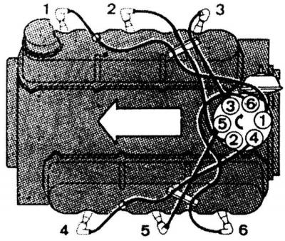
Numbering of cylinders and high-voltage wire connections
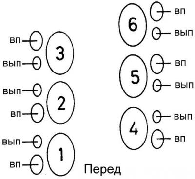
Valve arrangement
Adjustment of the intake and exhaust valves should be done with the engine cold at a temperature between 20° and 40°C. The size of the valve clearances is very important for achieving optimum engine performance. If the clearance is too large, the valves will not open sufficiently, and they will also open late and close early. If the clearance is too small, the valves will not close completely, which will lead to a lack of compression and very rapid burning of the valves and valve seats.
Adjusting valve clearances
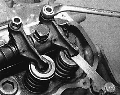
When adjusting valve clearances, turn the crankshaft only in the direction of engine rotation; rotate by placing the key on the pulley bolt.
1. Rotate the crankshaft to align the mark on the crankshaft pulley with the "O" shaped mark on the drive cover.
2. By gently rocking the pulley back and forth, you will notice that the valves of cylinder #1 or #5 are rocking (the two valve levers are moving in opposite directions). If the valves of cylinder #1 are rocking, rotate the crankshaft 360° so that the valves of cylinder #5 are rocking.
3. Having achieved the desired position of the valves of cylinder #5, check the valve clearances of cylinder #1 by installing a feeler gauge of a certain thickness between the valve lever and the valve stem. If the clearance needs to be adjusted, turn the adjusting screw of the valve lever until the desired clearance value is achieved. The clearances of the inlet and outlet valves have different values.
4. Now, if you turn the crankshaft 1/3 of a turn, the valves of cylinder #3 will swing, and you can check and adjust the valve clearances of cylinder #4.
5. Adjust the firing order clearances in the cylinders as follows (see table). Fig. Cylinder numbering and high-voltage wire connections shows the cylinder numbering order: the valves are numbered in the usual order, starting from the front of the engine (see Fig. Valve arrangement).
6. Install the valve cover gaskets and install the valve covers. Tighten the mounting bolts to the specified torque.
| The valves are swinging | Adjustable valves |
| cylinder no. 5 | cylinder #1 (inlet, outlet) |
| cylinder no. 3 | cylinder #4 (inlet, outlet) |
| cylinder no. 6 | cylinder #2 (inlet, outlet) |
| cylinder no. 1 | cylinder #5 (exhaust, intake) |
| cylinder no. 4 | cylinder #3 (exhaust, intake) |
| cylinder no. 2 | cylinder #6 (exhaust, intake) |
The material was copied from an information website: www.fordbook.ru