Contents: Removal ↳ Installation ↳
The process of removing the cylinder heads is presented for the engine installed in the car.
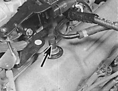
Oil pressure sensor
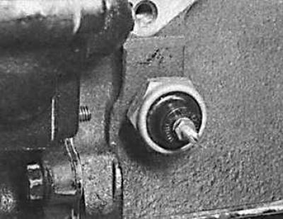
The oil pressure sensor is located on the left front side of the cylinder block.
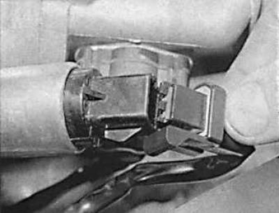
Front Air Flow Sensor Connector
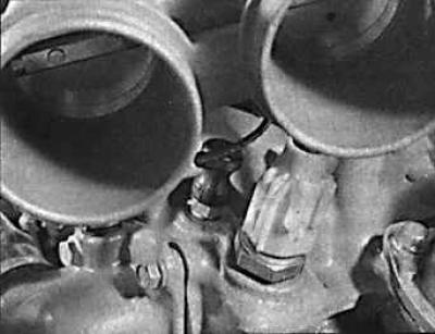
Coolant Temperature Sensor Location
Idle speed valve connector
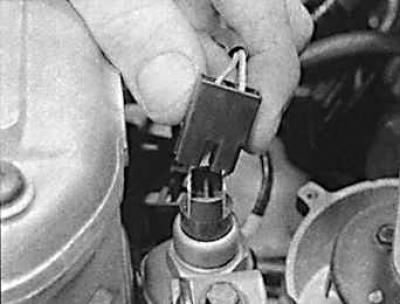
Ignition distributor connector
Fuel temperature sensor connector
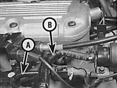
Fuel supply (A) and return (B) hoses
Removal
1. Remove the ground wire from the battery.
2. Drain the coolant from the cooling system.
3. Disconnect the upper radiator hose and heater hose from the thermostat housing.
4. Disconnect the air hoses from the throttle body.
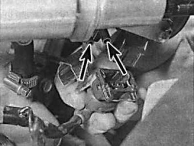
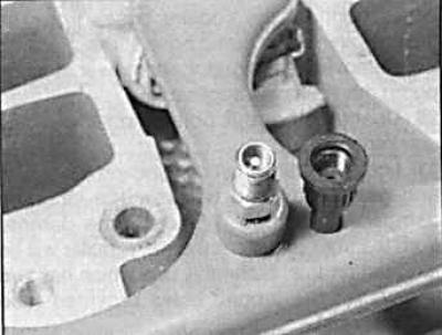
5. Remove the two connectors from the air flow sensors (the vacuum fittings are indicated by arrows).
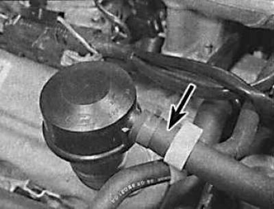
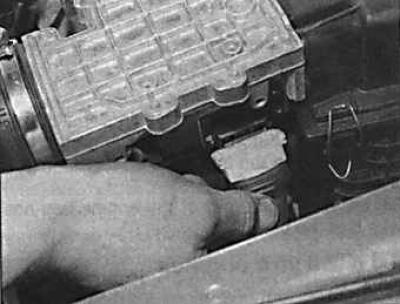
6. Remove the crankcase ventilation hose (indicated by the arrow) from the oil filler neck.
7. Remove the air filter housing together with the hoses and air flow sensors.
8. Disconnect the hoses from the expansion tank.
9. Disconnect electrical wires from the following components:
- generator (when removing the left head);
- coolant temperature sensor;
- idle speed valve;
- throttle position potentiometer;
- ignition distributor;
- fuel temperature sensor;
- fuel injectors.
10. Relieve the pressure in the fuel line (by pressing the pressure relief valve) and disconnect the fuel lines.
11. Disconnect the vacuum hoses from the fuel pressure regulator, throttle body and tee.
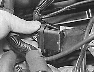
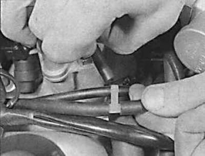
12. Remove the crankcase ventilation hose from the head cover (the hose valve is indicated by the arrow).
13. Unscrew the high pressure chamber and move it to the side together with the accelerator cable.
14. Remove the high-voltage wires from the spark plugs and remove the distributor cap together with the wires.
15. Turning the crankshaft by the central bolt of the vibration damper, set the piston of cylinder 1 to the ignition point (12° before TDC) and remove the ignition distributor.
16. To remove the right head, remove the drive belt, generator and power steering pump and attach them to the body with soft wire.
17. Remove the cylinder head cover.
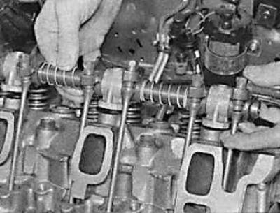
18. Unscrew the bolts and remove the rocker arm shaft.
19. Remove the tappets and arrange them in a manner that will allow them to be reinstalled in their proper positions.
20. Remove the intake manifold together with the fuel line and injectors.
21. Disconnect the exhaust pipes from the exhaust manifolds.
22. Disconnect the ground bus from the rear left side of the head.
23. Unscrew the spark plugs.
24. Gradually and consistently unscrew the cylinder head mounting bolts in the reverse order of their tightening.
25. Remove the cylinder head.
26. Remove the cylinder head gasket.
Installation
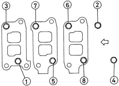
Intake Manifold Bolt Tightening Sequence
Installation is carried out in the reverse order of removal, taking into account the following points:
- replace the cylinder head mounting bolts with new ones;
- install only a new cylinder head gasket;
- apply sealant to the mating surfaces of the intake manifold and heads and tighten the intake manifold mounting bolts in a specific sequence;
- warm up the engine to operating temperature and check the ignition timing;
- tighten the intake manifold mounting bolts in a specific sequence.
(The full article is on the online resource FordBook)