|
STATES |
DETAILS/RESULTS/ACTIONS |
|
A1: INSPECTION OF TURBO ROTOR BLADES FOR DAMAGE |
|
|
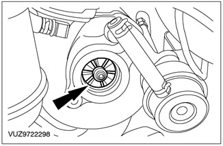
1 Disconnect the air filter outlet pipe from the turbocharger. |
|
|
2 Inspect the turbocharger rotor blades for damage. |
|
• Is there visible damage to the rotor blades? |
|
|
→ Yes |
|
|
Go to A2. |
|
|
→ No |
|
|
Go to A3. |
|
|
A2: CHECKING THE AIR INTAKE SYSTEM FOR FOREIGN MATERIAL |
|
|
1 Check air intake system components for signs of foreign material. |
|
|
• Are there any signs of foreign material? |
|
|
→ Yes |
|
|
CLEAN the air intake system components. INSTALL a new turbocharger. For more information, refer to Turbocharger - 75 HP Diesel Vehicles. or 90 hp / Turbocharger - Vehicles with 115 hp diesel engine available in this section. CHECK the system is working properly. |
|
|
→ No |
|
|
Go to A4. |
|
|
A3: CHECK TURBO BEARINGS FOR INCREASED PLAY |
|
|
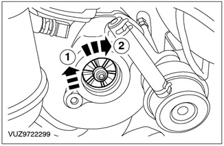
NOTE: A little play in the bearings is normal. |
|
|
1 Check that the turbocharger rotor rotates freely in the housing. - 1. With the turbocharger stationary, gently lift the shaft (the shaft will naturally lie in the lower sections of the bearings). - 2. Check that the turbocharger rotor rotates freely in the housing. |
|
• Does the rotor rotate freely in the housing? |
|
|
→ Yes |
|
|
GO to ch. "Fuel supply and controls", which describes further diagnosis of blue smoke. See Section 303-04A / 303-04B / 303-04C / 303-04D / 303-04E / 303-04F / 303-04G for more information. |
|
|
→ No |
|
|
INSTALL a new turbocharger. For more information, refer to Turbocharger - 75 HP Diesel Vehicles. or 90 hp / Turbocharger - Vehicles with 115 hp diesel engine available in this section. CHECK the system is working properly. |
|
|
A4: CHECKING TURBOCOMPRESSOR OIL SUPPLY LINE FOR CLOCKAGE |
|
|
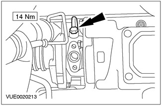
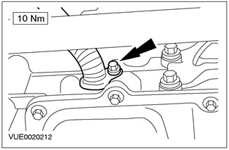
1 Disconnect the oil supply line from the turbocharger (for clarity, the catalytic converter and oil return line are shown in the removed position). |
|
2 Connect a small piece of known good hose to the oil supply line and carefully blow out the hose. |
|
|
• Are there any signs of blockage? |
|
|
→ Yes |
|
|
INSTALL a new turbocharger oil feed line. INSTALL a new turbocharger. For more information, refer to Turbocharger - 75 HP Diesel Vehicles. or 90 hp / Turbocharger - Vehicles with 115 hp diesel engine available in this section. CHECK the system is working properly. |
|
|
→ No |
|
|
INSTALL a new turbocharger. For more information, refer to Turbocharger - 75 HP Diesel Vehicles. or 90 hp / Turbocharger - Vehicles with 115 hp diesel engine available in this section. CHECK the system is working properly. |
|
PINPOINT TEST B: BLUE SMOKE WITHOUT INCREASED TURBO NOISE
|
STATES |
DETAILS/RESULTS/ACTIONS |
|
B1: TURBO OIL RETURN LINE INSPECTION |
|
|
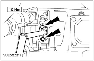
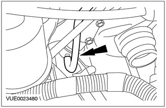
1 Disconnect the turbocharger oil return line from the turbocharger (catalytic converter not shown). |
|
2 Remove the turbocharger oil return line. |
|
3 Check the turbocharger oil return line for blockages or signs of damage. |
|
|
• Is the turbocharger oil return line OK? |
|
|
→ Yes |
|
|
GO to ch. "Fuel supply and controls", which describes further diagnosis of blue smoke. See Section 303-04A / 303-04B / 303-04C / 303-04D / 303-04E / 303-04F / 303-04G for more information. |
|
|
→ No |
|
|
INSTALL a new turbocharger oil return line. CHECK the system is working properly. |
|
PINPOINT TEST C: POOR ENGINE PERFORMANCE - VEHICLES WITH 75 HP DIESEL ENGINE OR 90 HP
|
STATES |
DETAILS/RESULTS/ACTIONS |
|
C1: CHECK TURBINE BYPASS VALVE ACTUATOR CONTROL PIPING FOR CLOCKAGE |
|
|
1 Remove the turbine bypass valve actuator control piping. |
|
|
2 Using a hand vacuum/pressure pump, connect one end to the turbine bypass actuator control line, operate the hand vacuum/pressure pump and observe the reading. |
|
|
• Is there an indication? |
|
|
→ Yes |
|
|
INSTALL a new turbine bypass valve actuator control line. CHECK the system is working properly. |
|
|
→ No |
|
|
Go to C2. |
|
|
C2: CHECK FOR LEAKAGE OF TURBINE BYPASS VALVE DIAPHRAGM ACTUATOR. |
|
|
1 Connect one end of the turbine bypass valve actuator control line to the turbine bypass valve actuator. |
|
|
2 Connect the other end of the turbine bypass valve actuator control line to the hand vacuum/charger pump. |
|
|
3 Operate the hand vacuum/pressure pump and observe the reading. |
|
|
• Does the pump hold a vacuum? |
|
|
→ Yes |
|
|
Go to C3. |
|
|
→ No |
|
|
INSTALL a new turbocharger. For more information, refer to Turbocharger - 75 HP Diesel Vehicles. or 90 hp available in this section. CHECK the system is working properly. |
|
|
C3: BOOST PRESSURE CHECK |
|
|
NOTE: Boost pressure is factory set and cannot be adjusted. |
|
|
1 Using a boost pressure gauge and a T-piece, connect a gauge between the turbo bypass valve actuator and the turbocharger. |
|
|
2 Start the engine and let it run until normal operating temperature is reached. |
|
|
3 Raise engine speed to 3000 rpm and observe readings. |
|
|
• Is the boost pressure less than 0.5 bar? |
|
|
→ Yes |
|
|
CHECK the fuel system. See Section 303-04A / 303-04B / 303-04C / 303-04D / 303-04E / 303-04F / 303-04G for more information. |
|
|
→ No |
|
|
INSTALL a new turbocharger. For more information, refer to Turbocharger - 75 HP Diesel Vehicles. or 90 hp available in this section. CHECK the system is working properly. |
|
PINPOINT TEST D: POOR ENGINE PERFORMANCE - VEHICLES WITH 115 HP DIESEL ENGINE
|
STATES |
DETAILS/RESULTS/ACTIONS |
|
D1: CHECK THE VACUUM LINE OF THE VACUUM DIAPHRAGM UNIT FOR CLOCKAGE |
|
|
1 Disconnect the vacuum line from the vacuum diaphragm assembly. |
|
2 Install the special tool and connect the vacuum line of the vacuum diaphragm unit. |
|
|
3 Operate the hand vacuum pump and observe the readings. |
|
|
• Is there an indication? |
|
|
→ Yes |
|
|
Go to D2. |
|
|
→ No |
|
|
INSTALL a new vacuum line to the vacuum diaphragm assembly. CHECK the system is working properly. |
|
|
D2: CHECK THE VACUUM DIAPHRAGM UNIT FOR LEAKAGE |
|
|
1 Install the special tool on the vacuum diaphragm assembly. |
|
|
2 Operate the hand vacuum pump and observe the readings. |
|
|
• Is the pump holding vacuum? |
|
|
→ Yes |
|
|
Go to D3. |
|
|
→ No |
|
|
INSTALL a new turbocharger. For more information, refer to Turbocharger - 115 HP Diesel Vehicles. available in this section. CHECK the system is working properly. |
|
|
D3: CHECKING VACUUM DIAPHRAGM UNIT ACTUATOR MOVEMENT |
|
|
1 Install the special tool on the diaphragm vane positioner. |
|
|
2 Operate the hand vacuum pump until a vacuum of 65 kPa is reached. Measure the distance traveled by the drive rod of the vacuum diaphragm assembly. |
|
|
• Does the drive rod of the vacuum diaphragm unit move within 9 - 11 mm? |
|
|
→ Yes |
|
|
REFER to WDS. |
|
|
→ No |
|
|
INSPECT for signs of damage or evidence of foreign material on turbocharger vanes. CHECK the system is working properly. |
|
Visitor comments