Contents: Removal ↳ Installation ↳
Special tool
 | Worldwide Diagnostic System (WDS) 418-F224 |
General equipment: Pneumatic vacuum gun.
| Name | Specification |
| Grease for nipple connection of high pressure fuel supply line |
Removal
All cars
WARNING: Do not smoke or carry a lighted cigarette or open flame of any type when working with or near fuel-related items. Highly flammable mixtures are always present in such situations and may ignite. Failure to follow these instructions may result in injury.
WARNING: This procedure involves handling fuel. Always be prepared for possible fuel splashing and follow fuel handling precautions. Failure to follow these instructions may result in personal injury.
WARNING: Do not carry out any repairs to the fuel injection system while the engine is running. Fuel pressure in the system can reach 1600 bar. Failure to follow these instructions may result in injury.
WARNING: Do not perform any repairs to the fuel injection system without verifying that the fuel pressure has dropped to zero and the fuel temperature has reached the outside temperature or below 30°C, whichever is greater. Failure to follow these instructions may result in personal injury.
WARNING: After stopping the engine, wait at least one minute before attempting any repairs to the fuel injection system. Failure to follow these instructions may result in injury.
CAUTION: Make sure that the service area where the vehicle is being worked on is as clean and dust-free as possible. Foreign matter from clutch, brake, machining or welding operations may contaminate the fuel system and cause subsequent malfunction.
CAUTION: Always perform the cleaning procedure before performing any repairs to fuel injection system components. Failure to follow this instruction may result in dirt entering the fuel injection system.
CAUTION: Diesel injection equipment is manufactured to very precise tolerances and with very small clearances. It is therefore especially important to maintain absolute cleanliness when working with these components. Open holes or lines should always be plugged using suitable plugs.
CAUTION: Do not disassemble the fuel injectors or clean their nozzles, even using ultrasonic cleaning. Always install new fuel injectors when necessary.
1. Using the Datalogger function of the Worldwide Diagnostic System (WDS), check that the fuel pressure has dropped to zero and the fuel temperature has reached the outside temperature or a temperature below 30°C, whichever is greater.
2. Disconnect the ground cable from the battery. For additional information, refer to Section 414-01.
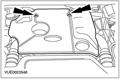
3. Remove the top engine cover.
4. Remove the air deflector.

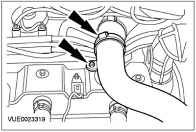
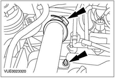
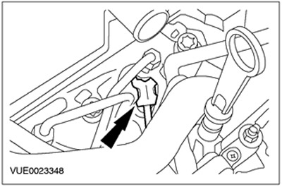
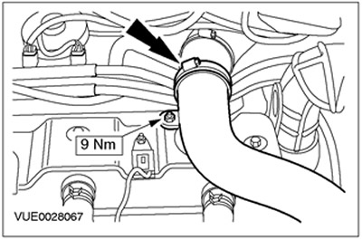
5. Disconnect the charge air cooler inlet pipe.
Cars with diesel engine 100 hp.
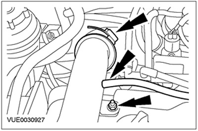
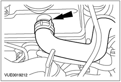
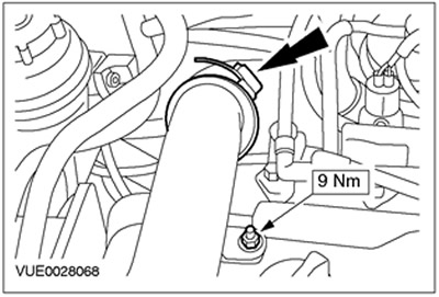
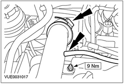
6. Disconnect the charge air cooler outlet pipe. Disconnect the vacuum line from the charge air cooler outlet pipe.
Cars with 115 hp diesel engine.
7. Disconnect the charge air cooler outlet pipe.
All cars
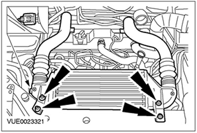
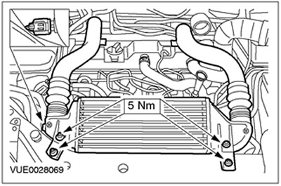
8. Disconnect the intake air temperature (IAT) sensor connector and remove the charge air cooler and lines.
9.
CAUTION: Protect the generator from contamination. Failure to follow this instruction may result in premature failure of the generator.
Cover the generator with a lint-free material to prevent contamination.
10.
CAUTION: Cover the fuel injector connectors with a lint-free material to prevent contamination from cleaning fluid.
Clean the fuel injector, high-pressure fuel supply line and surrounding areas. For more information, refer to the Cleaning Fuel Injection System Components chapter in this section.
11.
CAUTION: Do not allow engine oil to drip from the hose or valve cover onto the injector or high pressure fuel supply line.
Disconnect the positive crankcase ventilation (PCV) hose (this step is only required if fuel injector #4 is being removed).

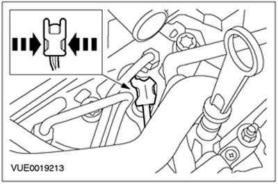
12. Disconnect the fuel return line from the fuel injector. Install a plug in the return port of the fuel injector.
13. Disconnect the fuel injector connector.
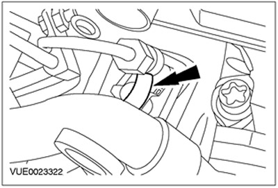
14.
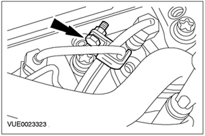
NOTE: Mark the orientation of the clamp to ensure it is installed in the exact same position.
Remove the high pressure fuel supply line clamp.
15.
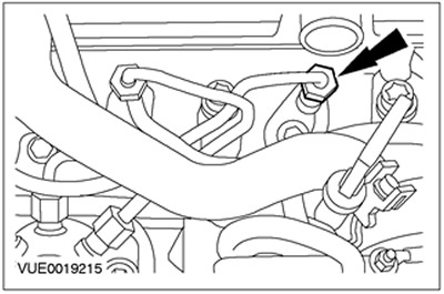
CAUTION: Make sure that the high pressure fuel supply line remains in contact with the fuel injector and fuel rail until both nipple connections have been disconnected and cleaned. Failure to follow this instruction may result in dirt entering the fuel injection system.
CAUTION: The high pressure fuel line nipple release tool should be installed on the top of the nipple as this is where most of the material is. Failure to follow this instruction may result in damage to the nipple connections.
Disconnect the high pressure fuel supply line from the fuel injector.
16.
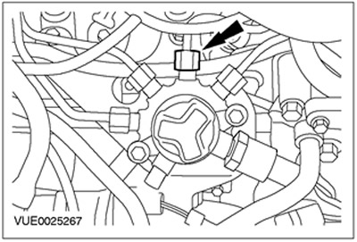
CAUTION: Make sure that the high pressure fuel supply line remains in contact with the fuel injector and fuel rail until both nipple connections have been disconnected and cleaned. Failure to follow this instruction may result in dirt entering the fuel injection system.
CAUTION: The high pressure fuel line nipple release tool should be installed on the top of the nipple as this is where most of the material is. Failure to follow this instruction may result in damage to the nipple connections.
Disconnect the high pressure fuel supply line from the fuel rail.
17.
CAUTION: Make sure that the high pressure fuel supply line remains in contact with the fuel injector and fuel rail until both nipple connections have been disconnected and cleaned. Failure to follow this instruction may result in dirt entering the fuel injection system.
Using an air vacuum gun, remove foreign material from the high pressure fuel supply line, fuel injector and fuel rail.
18. Remove the high pressure fuel supply line and discard it as no longer needed.
19. Using an air vacuum gun, remove foreign material from the fuel injector and fuel rail.
20. Install plugs into the open threaded holes of the fuel injector and fuel manifold.
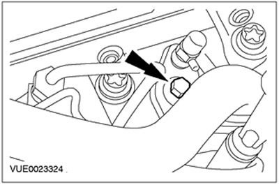
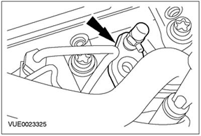
21. Remove the fuel injector clamp mounting bolt. Discard the bolt as it is no longer needed.
22. Clean the area around the fuel injector. For more information, refer to the Cleaning the Fuel Injection System Components section in this section.
23. Remove the fuel injector and clamp. Discard the fuel injector sealing washer as it is no longer needed.

Installation
All cars
WARNING: Do not smoke or allow a lighted cigarette or open flame of any type when working with or near fuel-related items. Highly flammable mixtures are always present in such situations and may ignite. Failure to follow these instructions may result in injury.
WARNING: This procedure involves handling fuel. Always be prepared for possible fuel splashing and follow proper fuel handling precautions. Failure to follow these instructions may result in injury.
CAUTION: Make sure that the service area where the vehicle is being worked on is as clean and dust-free as possible. Foreign matter from clutch, brake, machining or welding operations may contaminate the fuel system and cause subsequent malfunction.
CAUTION: Always perform the cleaning procedure before performing any repairs to fuel injection system components. Failure to follow this instruction may result in dirt entering the fuel injection system.
CAUTION: Diesel injection equipment is manufactured to very precise tolerances and with very small clearances. It is therefore especially important to maintain absolute cleanliness when working with these components. Open holes or lines should always be plugged using suitable plugs.
CAUTION: Do not disassemble the fuel injectors or clean their nozzles, even using ultrasonic cleaning. Always install new fuel injectors when necessary.
NOTE: Install a new fuel injector sealing washer.
NOTE: Install a new fuel injector clamp retaining bolt.
NOTE: Install a new high pressure fuel supply line.
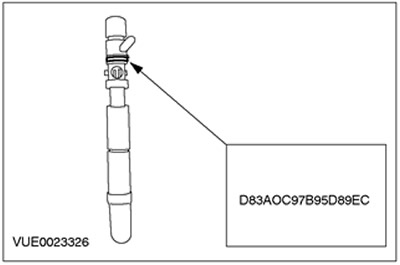
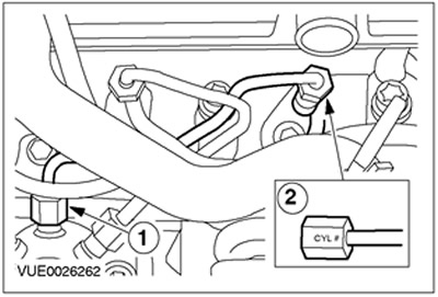
1. Write down the ID code of the new fuel injector to load into WDS when setting up the configuration (the figure shows the ID code as an example only).
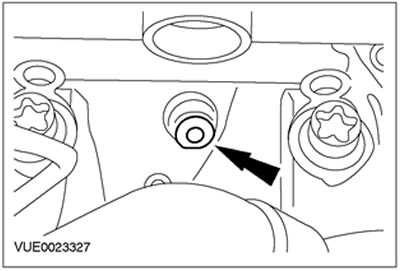
2. Install the new fuel injector sealing washer into the fuel injector recess in the cylinder head.
3. Remove the fuel injector nozzle cap and install the fuel injector and clamp. Discard the cap as it is no longer needed.
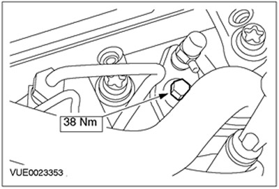
4. Install the new fuel injector clamp retaining bolt.
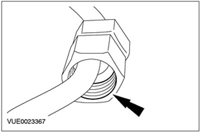
5. Lubricate the threads of the high pressure fuel supply line nipple connections using clean grease.
6.
CAUTION: Protect the generator from contamination. Failure to follow this instruction may result in premature failure of the generator.
Cover the generator with a lint-free material to prevent contamination.
7.
CAUTION: Do not strike the ends of the high pressure fuel supply line. Failure to do so may result in damage to the ends of the fuel line and foreign material being introduced into the fuel injection system.
CAUTION: Remove the plugs from the high-pressure fuel supply line, fuel injector and fuel rail as late as possible. Failure to do so may result in dirt entering the fuel injection system.
NOTE: To facilitate identification of the high pressure fuel supply lines, the connections on the fuel injector side are engraved with the cylinder number.
NOTE: Do not tighten the high pressure fuel supply line nipple connections at this stage.
NOTE: Apply pressure to the high pressure fuel supply line to keep the fuel line nipple in contact with the fuel injector cone when connecting.
NOTE: If the new high pressure fuel supply line cannot be installed correctly, the remaining high pressure fuel supply lines must be removed and the fuel rail must be released to ensure correct alignment. For additional information, refer to the Fuel Rail chapter in this section.
Install a new high pressure fuel supply line.
- 1. Connect the high pressure fuel supply line to the fuel rail.
- 2. Connect the high pressure fuel supply line to the fuel injector.
- Discard the plugs as they are no longer needed.
8.
NOTE: Ensure that the clamp is installed in the same position as it was before removal.
Install the high pressure fuel supply line clamp.

9.
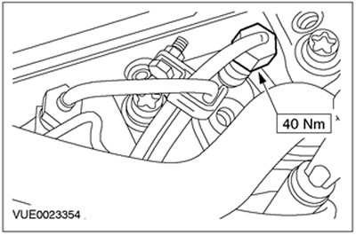
CAUTION: The high pressure fuel line nipple tightening tool should be positioned on the top of the nipple joint as this is where most of the material is. Failure to follow this instruction may result in damage to the nipple joint.
Tighten the high pressure fuel supply line nipple connection to the fuel injector.
10.
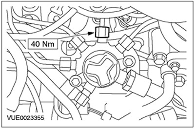
CAUTION: The high pressure fuel line nipple tightening tool should be positioned on the top of the nipple joint as this is where most of the material is. Failure to follow this instruction may result in damage to the nipple joint.
Tighten the high pressure fuel supply line nipple connection to the fuel rail.
11. Remove the plug from the fuel injector return port and connect the fuel injector return line. Discard the plug as it is no longer needed.

12. Connect the fuel injector connector.
13. Connect the positive crankcase ventilation (PCV) hose (this step is only required if fuel injector #4 is being removed).
14. Remove the lint-free material from the generator.
15. Install the charge air cooler and lines and connect the IAT sensor plug.
Cars with 115 hp diesel engine.
16.
CAUTION: Make sure the inside of the end of the charge air cooler outlet pipe is clean and free of oil, as this will reduce adhesion when connecting the pipe to the charge air cooler. Failure to follow this instruction may result in engine damage.
Connect the charge air cooler outlet pipe.
Cars with diesel engine 100 hp.
17.
CAUTION: Make sure the inside of the charge air cooler outlet pipe end is clean and free of oil, as this will reduce adhesion when connecting the pipe to the charge air cooler. Failure to follow this instruction may result in engine damage.
Connect the outlet pipe to the charge air cooler. Connect the vacuum line to the outlet pipe of the charge air cooler.
All cars
18.
CAUTION: Make sure that the inside of the charge air cooler intake pipe is clean and free of oil, as this will impair the bond between the pipe and the charge air cooler. Failure to follow this instruction may result in engine damage.
Connect the charge air cooler inlet pipe.
19. Install the air deflector.
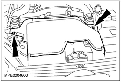
20. Install the top engine cover.

21. Connect the ground cable to the battery. Refer to Section 414-01 for additional information.
22. Using WDS, configure the new fuel injector relative to the injector control module.