Special tool
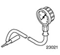 | Boost pressure gauge 310 - 020 (23 - 021) |
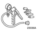 | Manual vacuum/pressure pump 416 - D001 (23 - 036A) |
How it works - Vehicles with a 75 hp diesel engine. or 90 hp
The turbocharger is controlled by a turbine bypass valve. The turbine bypass valve bypasses part of the exhaust gases behind the turbine and therefore acts as a regulator. The turbine bypass valve is pre-set at vehicle assembly and cannot be adjusted later.
How it works - Vehicles with a 115 hp diesel engine.
The turbocharger is designed to improve engine power and performance. The list below details problems related to turbocharger operation.
- A high engine speed results in an increased turbine speed and therefore the turbocharger generates excessive boost pressure.
- Low engine speed results in insufficient turbine speed and therefore the turbocharger does not generate sufficient boost pressure.
The variable turbocharger does not have a turbine bypass valve. Instead, it has adjustable vanes that are housed in the turbocharger's turbine housing. The turbocharger vanes act as the turbocharger's boost pressure control.
The variable turbocharger delivers full boost pressure over the entire engine speed range, not just at high engine speeds. This is achieved by adjusting the position of the vanes and, as a result, changing the exhaust gas flow rate.
The flow rate of the exhaust gas is increased independently of the engine speed by changing the cross-section of the intake port upstream of the turbocharger turbine. This allows the turbocharger turbine to spin faster. Higher turbocharger speed creates high turbocharger boost pressure at all engine speeds.
The turbocharger vanes are controlled by the powertrain control module (PCM). REFER to WDS to diagnose turbocharger vanes.
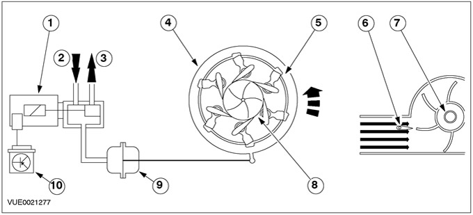
Adjustment at low engine speed
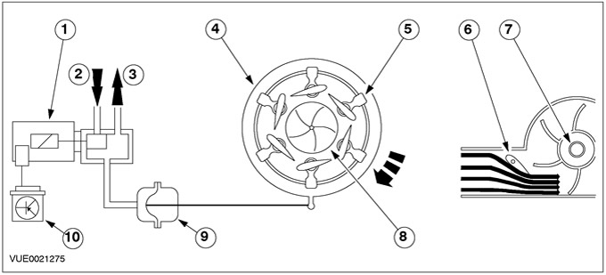
| Pos. | Spare Part No | Name |
| 1 | - | Solenoid valve for adjusting the position of the blades |
| 2 | - | Atmosphere pressure |
| 3 | - | Vacuum |
| 4 | - | adjusting ring |
| 5 | - | blades |
| 6 | - | blades |
| 7 | - | Turbine |
| 8 | - | Turbine |
| 9 | - | Vacuum Diaphragm Block |
| 10 | - | RSM |
At low engine speeds, the PCM activates the vane position solenoid valve to provide vacuum access. The vacuum diaphragm unit moves the adjusting ring so that the blades are set at a low slip angle. The small intake cross-section that is created for the exhaust gas flow allows the turbocharger boost pressure to rise quickly and easily at low engine speeds.
Adjustment at an average frequency of rotation of the crankshaft of the engine
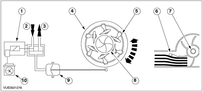
| Pos. | Spare Part No | Name |
| 1 | - | Solenoid valve for adjusting the position of the blades |
| 2 | - | Atmosphere pressure |
| 3 | - | Vacuum |
| 4 | - | adjusting ring |
| 5 | - | blades |
| 6 | - | blades |
| 7 | - | Turbine |
| 8 | - | Turbine |
| 9 | - | Vacuum Diaphragm Block |
| 10 | - | PCM |
Adjustment at maximum engine speed
| Pos. | Spare Part No | Name |
| 1 | - | Vane adjustment solenoid valve |
| 2 | - | Atmosphere pressure |
| 3 | - | Vacuum |
| 4 | - | adjusting ring |
| 5 | - | blades |
| 6 | - | blades |
| 7 | - | Turbine |
| 8 | - | Turbine |
| 9 | - | Vacuum Diaphragm Block |
| 10 | - | PCM |
As the engine speed increases, the cross-sectional area of the intake duct upstream of the turbocharger turbine continuously increases. The turbine speed, and therefore the amount of air supplied to the engine, is adjusted to match the engine speed. This means that the turbocharger boost pressure remains optimized over the entire engine speed range.
Maximum position of the turbocharger blades (maximum cross-sectional area in the open position) - this is also an emergency position, for example, in the event of an electrical problem or a leak in the vacuum system. Therefore, there is little chance of engine damage due to overboost in the event of a turbocharger control problem.
Visitor comments