Contents: Removal ↳ Installation ↳
Special tool
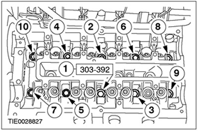
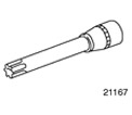 | Socket wrench for cylinder head bolts 303-392 (21-167) |
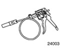 | Hose Clamp Remover/Installer 303-397 (24-003) |
General equipment: Spatula.
| Name | Specification |
| Sealant remover | WSK-M2G348-A4 |
| Motor oil | WSS-M2C912-A1 |
Removal
1. Disconnect the battery. For additional information, refer to Section 414-01.
2. Relieve fuel system pressure. Refer to Section 310-00A for additional information.
3.
WARNING: To avoid scalding, cover the filler cap of the expansion tank with a thick cloth before opening the cooling circuit. Failure to follow this instruction may result in injury.
Relieve pressure in the cooling system.
4. Raise and support the vehicle. Refer to Section 100-02 for additional information.
5. Drain the coolant from the radiator.
- Allow the coolant to drain into a suitable container.
- After draining the coolant, install the radiator drain plug.
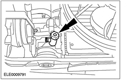
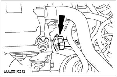
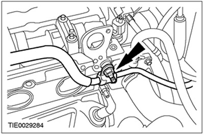
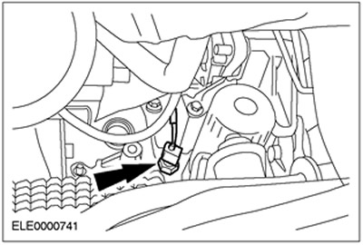
6. Disconnect the electrical connector of the oil pressure switch.

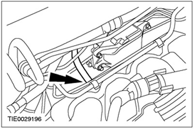
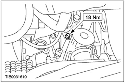
7. Remove the lower intake manifold mounting bolt.
8. Remove the accessory drive belt. Refer to Section 303-05 for additional information.
9. Lower the vehicle.
10. Remove the air cleaner. Refer to Section 303-12 for additional information.
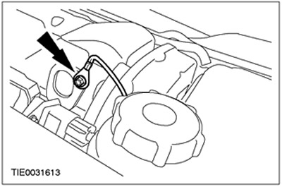
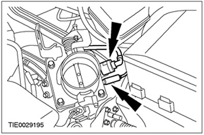
11. Disconnect the brake booster line from the intake manifold. Release the quick release coupling and disconnect the brake booster line.
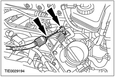
12. Disconnect the accelerator cable from the throttle body.

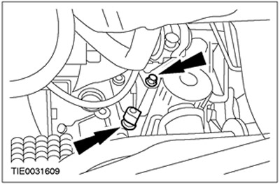
13. Disconnect the vacuum hoses from the intake manifold.

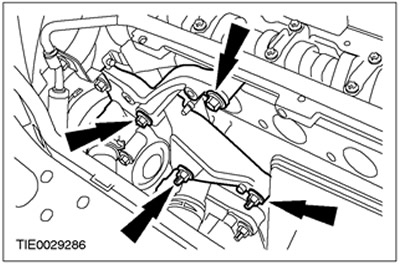
14. Disconnect the fuel injector wiring harness plug connectors.
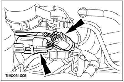
15. Disconnect the camshaft position sensor connector.
16.
WARNING: Fuel leakage. Handle fuel with care.
Disconnect the fuel lines.
17. Disconnect the ground cable from the lifting eye.
18. Remove the exhaust manifold. For more information, refer to the Exhaust Manifold chapter in this section.
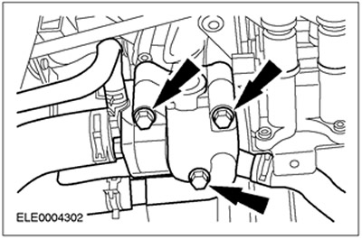
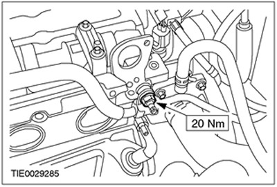
19. Disconnect the thermostat housing.
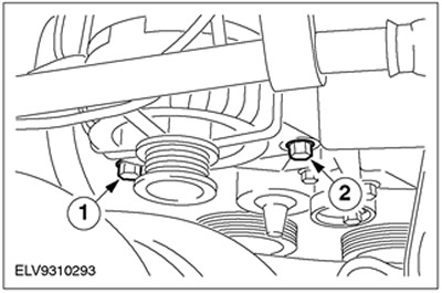
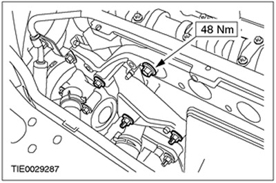
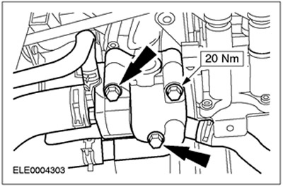
20. Disconnect the power steering pipe bracket from the cylinder head.
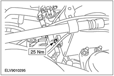
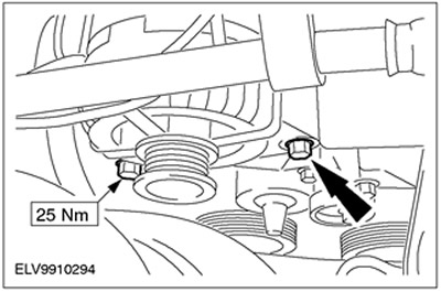
21. Disconnect the power steering pump bracket from the cylinder head and cylinder block.
22. Disconnect the generator.
- 1.Loosen the bolt.
- 2. Unscrew the bolt.
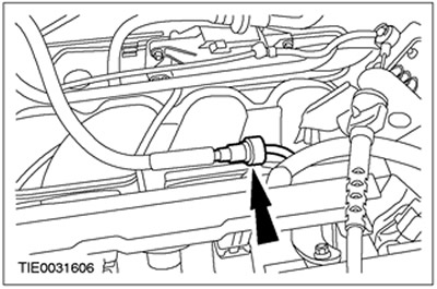
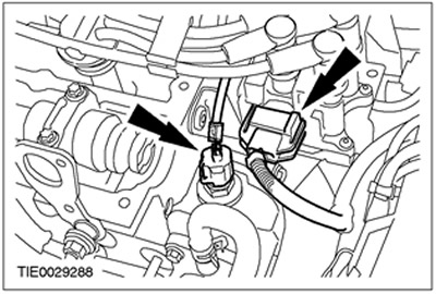
23. Disconnect the wiring harness from the Electronic Ignition (EI) coil and from the Engine Coolant Temperature (ECT) sensor.

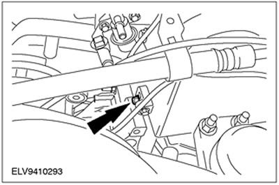
24. Remove the upper generator bracket bolt.
25. Remove the camshafts.
26.
CAUTION: Cylinder head bolts can only be used twice; mark the bolts to indicate that they were used.
CAUTION: The cylinder head must be cooled to outside temperature.
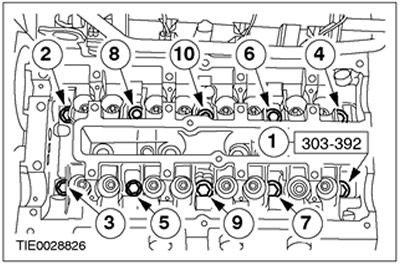
NOTE: Loosen the cylinder head bolts evenly, working in the sequence shown.
Remove the cylinder head bolts.
27. Remove the cylinder head.
Installation
1. Remove any remaining gasket material using a sealant remover and a spatula. Thoroughly clean the threaded holes for the cylinder head bolts.
2. Inspect the cylinder head for warpage. Refer to Section 303-00 for additional information.
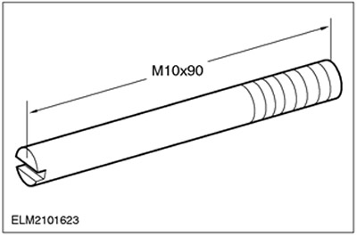
3. Make two guide pins as shown in the figure.
4.
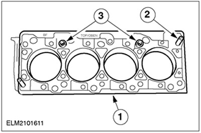
NOTE: Install a new cylinder head gasket.
Install the cylinder head gasket.
- 1.Install the cylinder head gasket.
- 2. Insert the prepared guide pins.
- 3. Check that the guide pins are installed correctly.
5. Install the cylinder head.
6.
CAUTION: Do not overtighten the cylinder head bolts.
Tighten the cylinder head bolts in three stages in the sequence shown.
- Stage 1: 20 Nm
- Stage 2: 40 Nm
- Stage 3: 90 degrees
7.
NOTE: Before installing the valve lifters, coat them with clean engine oil.
Install the valve lifters.
8. Install the camshafts.
9. Lower the vehicle.
10. Connect the power steering pump bracket to the cylinder head and cylinder block.
11. Install the generator bracket bolt.
12. Connect the wiring harness to the Electronic Ignition (EI) coil and the Engine Coolant Temperature (ECT) sensor.
13. Connect the generator.
14. Connect the power steering pipe bracket to the cylinder head.
15.
NOTE: Install a new thermostat housing gasket.
Install the thermostat housing.
16. Connect the fuel lines.

17. Connect the camshaft position (CMP) sensor connector.

18. Connect the fuel injector wiring harness plug connectors.

19. Connect the accelerator cable and speed control cable (if equipped) to the throttle body.
20. Connect the vacuum hoses to the intake manifold.
21. Connect the brake booster line to the intake manifold.

22. Install the exhaust manifold. For more information, refer to the Exhaust Manifold chapter in this section.
23. Install the lower intake manifold mounting bolt.
24. Connect the oil pressure switch plug connector.
25.
NOTE: Install a new oil filter.
Drain the engine oil.
26. Lower the vehicle.
27. Install the air cleaner. Refer to Section 303-12 for additional information.
28. Fill the engine with engine oil.
29. Fill the cooling system with coolant and bleed the system. Refer to Section 303-03 for additional information.
The original can be found on this resource: www.FordBook.ru