Special tool
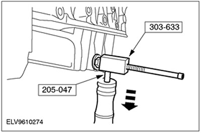
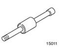 | Hammer with moving hammer 205-047 (15-011) |
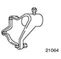 | Support bracket for 303-435 303-435-04 (21-064) |
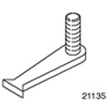 | Flywheel locking tool 303-254 (21-135) |
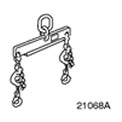 | Engine lift bracket 303-122 (21068A) |
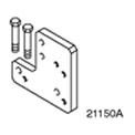 | Base plate for 303-435-04 303-435-12 (21-150A) |
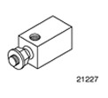 | Adapter for 205-047 303-633 (21-227) |
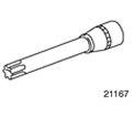 | Socket wrench for cylinder head bolts 303-392 (21-167) |
General equipment: Assembly stand.
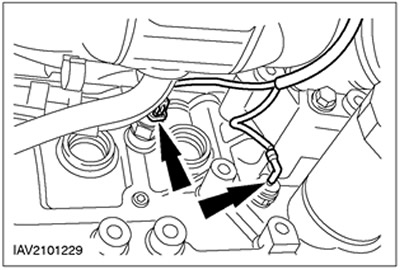
1. Disconnect the plug connectors of the oil pressure switch and the knock sensor (KS).
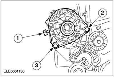
2. Remove the generator.
- 1.Disconnect the positive wire.
- 2. Remove the bolt.
- 3. Remove the bolt.
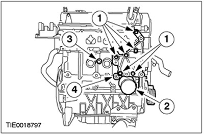
3. Remove the accessories from the intake side.
- 1. Generator support bracket.
- 2.Oil filter
- 3.Knock sensor (KS)
- 4. Oil pressure switch
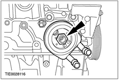
4. Remove the oil cooler.
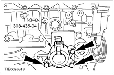
5. Install the base plate on the engine.

6. Install the support bracket on the base plate.
7. Mount the engine on the assembly stand and remove the engine lift bracket.
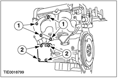
8. Remove the accessories from the exhaust side.
- 1. Power steering pump bracket.
- 2. Air conditioning compressor bracket.
9. Disconnect the forced crankcase ventilation.
10. Remove the clutch assembly. See Section 308-01A / 308-01B / 308-01C for more information.
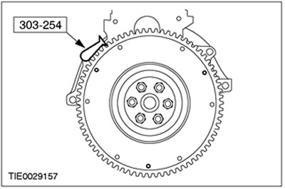
11. Using the special tool, lock the flywheel in a stationary position.
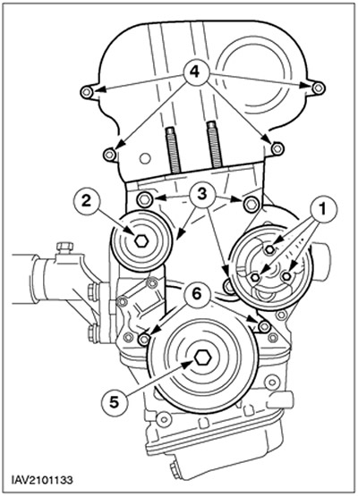
12. Remove the timing belt cover.
- 1.Water pump pulley
- 2. Intermediate pulley drive belt
- 3. Front engine mount bracket.
- 4.Top timing belt cover
- 5.Remove the damper from the crankshaft pulley.
- 6.Lower timing belt cover
13.
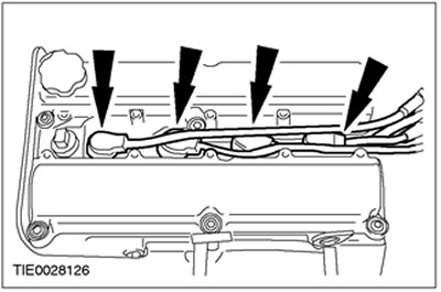
CAUTION: Do not pull on spark plug wires when disconnecting spark plug connectors. To prevent damage to the wires, disconnect the ignition wires from the ignition coils if necessary. Turn the spark plug connectors slightly before disconnecting them to loosen the seals.
CAUTION: Disconnect the spark plug connectors according to the location of the spark plugs.
Disconnect the spark plug connectors.
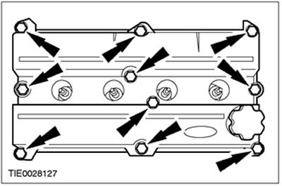
14. Remove the valve cover.
15.
NOTE: Installation position of crankshaft pulley and thrust washer.
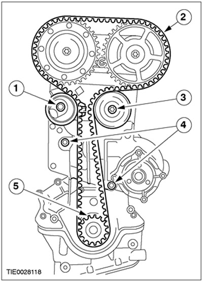
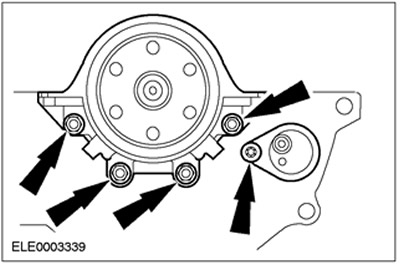
Remove the timing belt drive and water pump.
- 1. Release the timing belt tensioner by turning it counterclockwise and remove it.
- 2.Remove the timing belt.
- 3.Remove the intermediate pulley (idler pulley).
- 4.Remove the water pump.
- 5.Remove the pulley and thrust washer from the crankshaft.
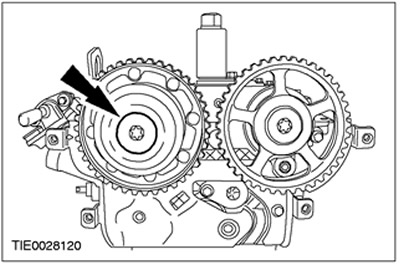
16.
NOTE: To prevent the camshaft from turning, hold it by the hex key using an open end wrench.
Remove the intake camshaft pulley cap.
17.
NOTE: To prevent the camshaft from turning, hold it by the hex key using an open end wrench.
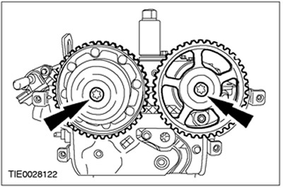
Remove the camshaft pulleys.
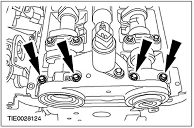
18. Remove the oil supply flange.
- Discard the camshaft oil seals as they are no longer needed.
- Discard the oil seal of the oil supply flange as it is no longer needed.
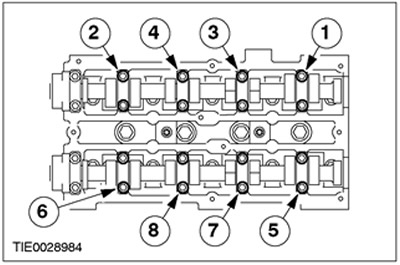
19.
CAUTION: Loosen and remove the camshaft bearing cap bolts in the sequence shown.
NOTE: Working in this sequence in several steps, loosen each bolt evenly two turns at a time.
Remove camshafts. Remove the valve lifters and set them aside.
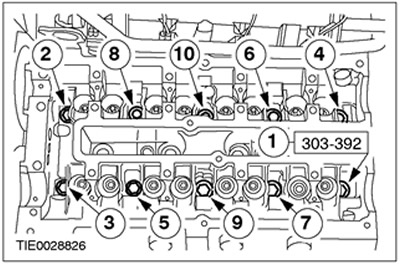
20.
CAUTION: Bolts can be reused twice, mark bolts with center punch.
CAUTION: Remove the cylinder head bolts in the sequence shown.
Remove the cylinder head.
21. Using the special tool, remove the flywheel. Discard the bolts as they are no longer needed.
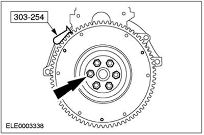
22. Remove the special tool.
23. Remove the drain plug and remove the oil sump mounting bolts. Allow the oil to drain into a suitable container.
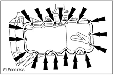
24.
CAUTION: To prevent damage to the sealing surfaces, use only the special tool shown to remove the oil pan.
NOTE: Tighten the jam nut on the oil sump and hit with a special tool several times to separate the oil sump from the bottom section of the crankcase.
Using the special tool, remove the oil pan.
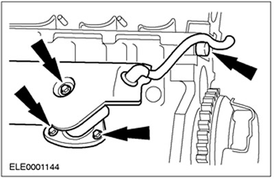
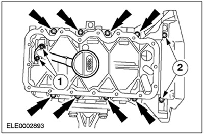
25. Remove the oil inlet line and lower crankcase section.
- 1. Oil intake pipe bolts
- 2. Bolts of the lower section of the crankcase
26. Remove the oil pump.

27. Remove the crankshaft rear oil seal retainer, crankshaft position sensor (CKP) and CKP bracket.
Visitor comments