Special tool
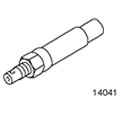 | Axle shaft installer 204-161 (14-41) |
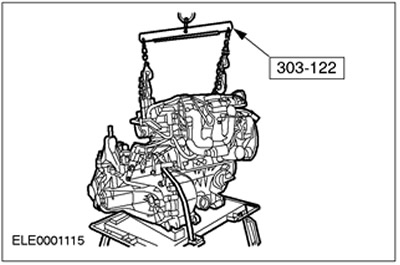
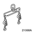 | Engine lift bracket 303-122 (21068A) |
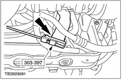
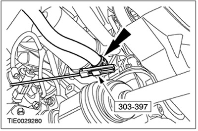
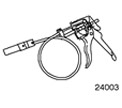 | Coolant hose clamp remover/installer 303-397 (24-003) |
General Equipment
- Fixing clamp
- assembly table
| Name | Specification |
| Engine oil | WSS-M2C912-A1 |
All cars
1. Install the gearbox in the block with the drive axle.
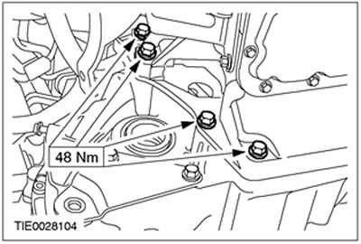
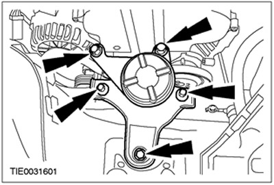
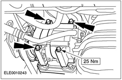
2. Establish the left bolts of fastening of a transmission in the block with the leading bridge.
3. Establish the right bolts of fastening of a transmission in the block with the leading bridge.
4. Connect the starter to the gearbox in the block with the drive axle.
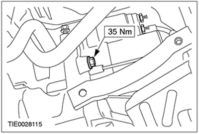
5. Establish the top bolts of fastening of a starter. Connect the ground cable to the transaxle box.
6. Establish the top bolts of fastening of a transmission in the block with the leading bridge.
7.
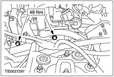
NOTE: Install a new exhaust flange gasket and new nuts.
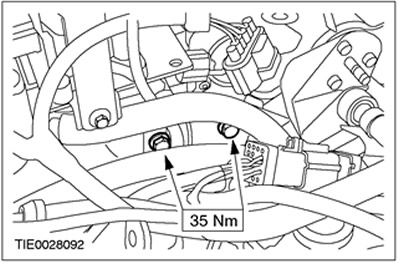
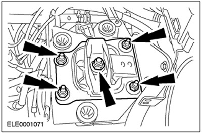
Connect the catalytic converter to the exhaust manifold.
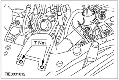
8. Install the catalytic converter bracket.
9. Use the fixing collar to fix the gearbox on the assembly table. Remove special tools.
10. Raise and support the vehicle. See Section 100-02 for more information.
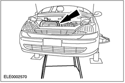
11. Position the engine/transmission assembly under the vehicle. Lower the car carefully.
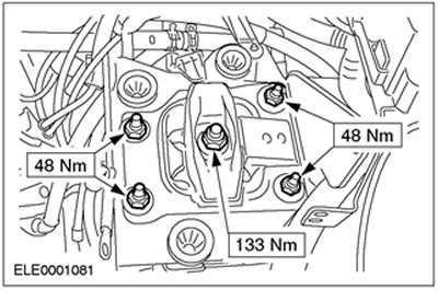
12.
NOTE: Do not tighten the front engine mount bolts and nuts at this stage.
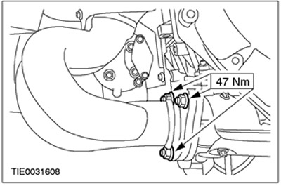
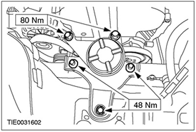
Install the front engine mount.
13.
NOTE: Do not tighten rear engine mount bolts at this stage.
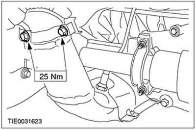
Install the rear engine mount.
14. Remove the retaining strap from the engine/gearbox assembly and remove the assembly table.
15. Raise and support the vehicle. See Section 100-02 for more information.
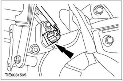
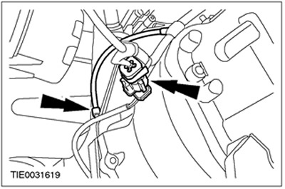
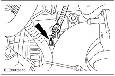
16. Dock an electric socket of the switch of lanterns of a backing. Clip on the wiring harness.
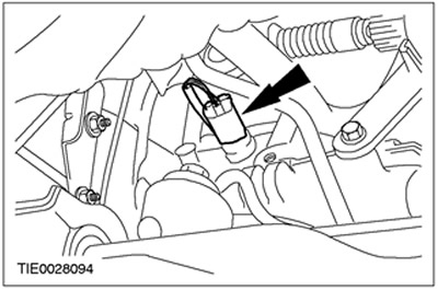
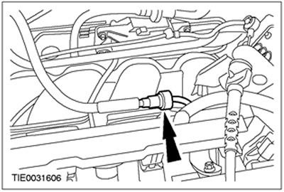
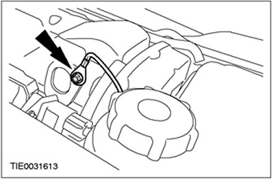
17. Connect the vehicle speed sensor connector (VSS).
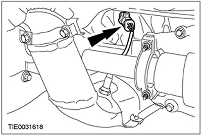
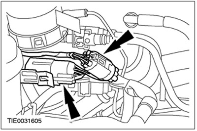
18. Connect heated oxygen sensor connectors (H02S) and crankshaft position sensor (CKP).
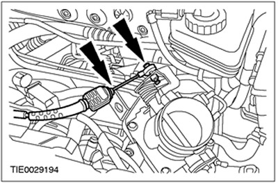
19. Connect the catalytic converter monitoring oxygen sensor connector.
20.
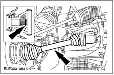
CAUTION: Support axle shaft. The inner hinge should not be tilted more than 18 degrees. External hinge - at an angle exceeding 45 degrees.
CAUTION: Be careful not to damage the axle shaft oil seal.
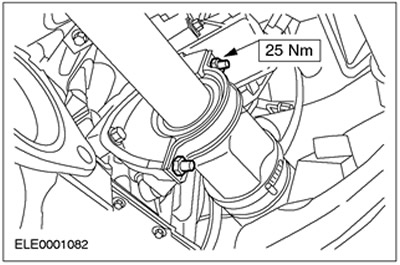
NOTE: Install a new intermediate shaft intermediate bearing cover and locknuts.
Connect the right axle shaft and the intermediate shaft to the gearbox in the block with the drive axle. Install the intermediate support cover.
21.
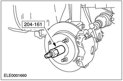
CAUTION: The drive shaft nut can be reused four times; check the markings on the nut and replace the nut if necessary.
NOTE: Do not tighten the axle shaft nut at this stage.
Using the special tool, insert the axle shaft into the wheel hub.
22.
CAUTION: Support axle shaft. The inner hinge should not be tilted more than 18 degrees. External hinge - at an angle exceeding 45 degrees.
CAUTION: Be careful not to damage the axle shaft oil seal.
CAUTION: Make sure the snap ring is installed correctly.
NOTE: Install a new circlip.
Connect the left axle shaft to the gearbox in the block with the drive axle.
23. Install the cross member. See Section 502-00 for more information.
24. Establish a flexible insert of system of release.
25. Lower the car.
26. Tighten the nuts and bolts of the rear engine mount.
27. Tighten the front engine mount nuts.
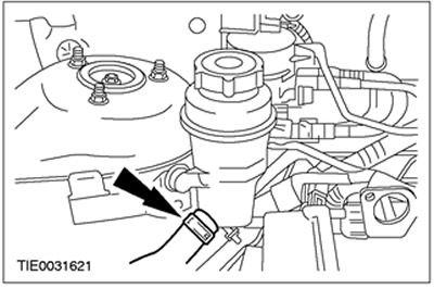
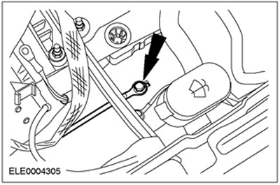
28. Connect the power steering supply hose to the power steering reservoir.
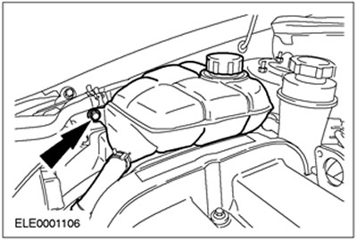
29. Install the expansion tank of the cooling system.
30. Raise and support the vehicle. See Section 100-02 for more information.
31. Connect the bottom hose to the radiator.
32. Connect the coolant hose to the oil cooler.
Vehicles with air conditioning
33. Install the air conditioning compressor.
All cars
34. Put on the accessory drive belt. See Section 303-05 for more information.
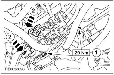
35. Connect the shift cables to the gearbox in the block with the drive axle.
- 1. Connect the bracket to the gearbox in the block with the drive axle.
- 2. Connect the shift cable and gear selection cable to the gear selector levers.
36. Adjusting the shift cable. See Section 308-00 for more information.
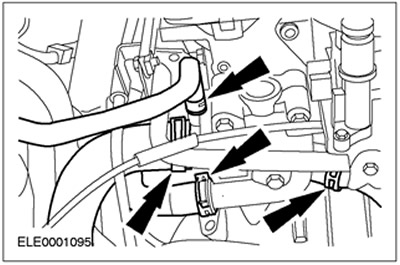
37. Connect the coolant hoses to the thermostat housing.
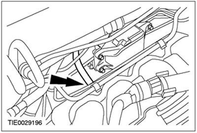
38. Connect the fuel lines to the fuel manifold.
39. Connect the pipeline of the vacuum amplifier of brakes to an inlet collector.
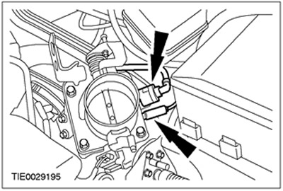
40. Connect the vacuum hoses to the throttle body.
41. Dock the electrical connectors of the wiring harness.
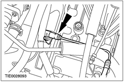
42.
WARNING: Brake fluid leakage. Do not allow brake fluid to come into contact with skin or eyes. If brake fluid comes into contact with the skin or eyes, immediately rinse the affected area with water.
WARNING: If brake fluid comes into contact with body paint, immediately flush the affected area with water.
Connect the clutch supply line to the clutch slave cylinder. Install the clamp.
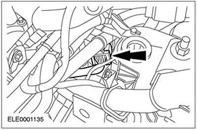
43. Connect the alternator connector.
44. Connect the plug connectors of the fuel injector wiring harness.
45. Connect the ground cable to the engine lift lug.
46. Connect the accelerator cable and speed control cable (in the presence of) to the throttle body.
47. Install the air cleaner intake piping and resonator.
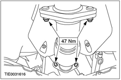
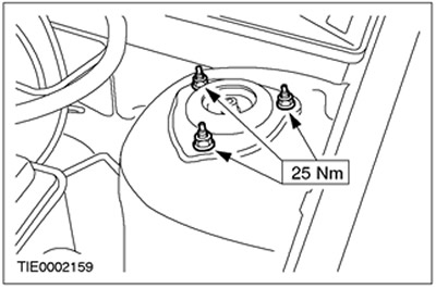
48. Tighten the nuts securing the upper support of the rack assembly with the spring (at both sides).
49. Connect the ground cable to the inner wing.
50. Install the air filter. See Section 303-12 for more information.
51. Connect the positive battery cable to the battery terminal.
52.
CAUTION: After disconnecting and reconnecting the battery wires, some signs of abnormal driving behavior may appear as the vehicle learns its adaptive strategy. A car needs to travel at least 16 km to learn its working strategy (10 miles).
Install the battery tray. See Section 414-01 for more information.
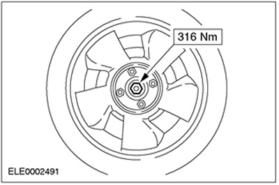
53. Install the right front wheel. See Section 204-04 for more information.
54. Tighten the axle stud nuts.
55. Add working fluid to the cooling system. See Section 303-03 for more information.
56. Fill the transaxle with manual transmission fluid. See Section 308-00 for more information.
57. Fill the engine with engine oil.
58. Remove air from the hydraulic clutch. See Section 308-00 for more information.
59. Prime and bleed the PAS system. See Section 211-00 for more information.
Visitor comments