Special tool
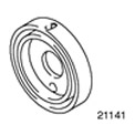 | Crankshaft Rear Oil Seal Installer 303-291 (21-141) |
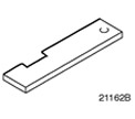 | Torque Distribution Template, Camshaft Alignment 303-376 (21-162V) |
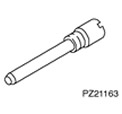 | Pin for setting the distribution of moments, TDC of the crankshaft 303-574 (21-163) |
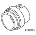 | Timing Cover Oil Seal Installer 303-039 (21-009V) |
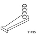 | Flywheel locking tool 303-254 (21-135) |
General equipment: Steel ruler.
| Name | Specification |
| sealant | WSK-M4G320-A |
| sealant | WSK-M2G348-A5 |
| sealant | WSS-M4G323-A7 |
| Engine oil | WSS-M2C912-A1 |
| Silicone Grease | A960-M1S171-AA |
1.
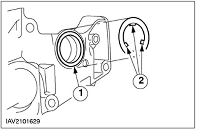
NOTE: Install a new crankshaft rear oil seal retainer gasket.
NOTE: Do not fully tighten the crankshaft rear oil seal retainer bolts at this point.
Install the rear oil seal retainer.
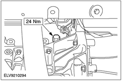
2. Install the crankshaft position sensor (TFR) and mounting bracket.
3.
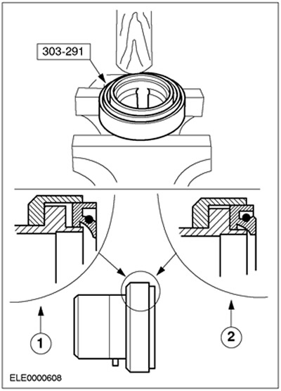
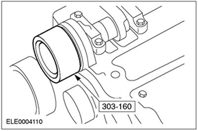
CAUTION: The oil seal must be fully inserted into the special tool.
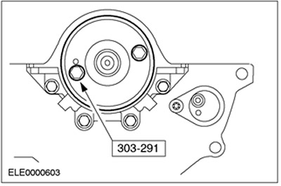
Insert a new crankshaft rear oil seal into the special tool.
- To ensure proper installation, hold the special tool in a vise and insert the oil seal using a hammer handle when installing.
- 1.Wrong installation
- 2.Proper installation
4.
NOTE: Install a new crankshaft rear oil seal.
Using the special tool and two old flywheel bolts, install the crankshaft rear oil seal.
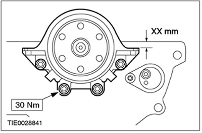
5. Align the position of the crankshaft rear oil seal holder so that the sealing surface of the oil seal holder is 0.3 mm - 0.8 mm below the cylinder block, and tighten the mounting bolts.
6. Remove the special tool.

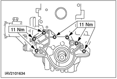
7.
NOTE: Install a new oil pump gasket.
NOTE: Do not fully tighten the oil pump mounting bolts at this stage.
Install the oil pump.
8. Align the position of the oil pump on both sides so that the mating surface is located at a distance of 0.3 mm - 0.8 mm above the lower edge of the cylinder block.
9. Tighten the oil pump mounting bolts.
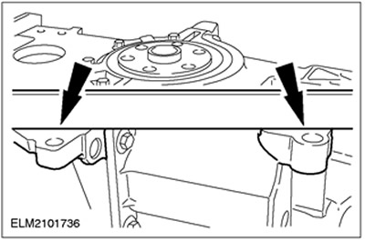
10.
NOTE: The lower crankcase mounting must be tightened to the specified torque no later than 10 minutes after the sealant has been applied.
NOTE: If the allowable overhang or clearance is exceeded, install shims as described below.
Align the position of the lower section of the crankcase.
- Using a straightedge, align the lower crankcase so that the cylinder block and lower crankcase are flush, or no more than 0.10mm protrusion or 0.25mm clearance.
- Apply sealant to the connections between the cylinder block and the oil pump oil seal holder.
- Install the lower crankcase with a new gasket and hand tighten the bolts.
11. Install lower crankcase shims if necessary.
- if there is a gap of 0.26 - 0.50 mm, install a 0.25 mm shim.
- if there is a gap of 0.51 - 0.75 mm, install a 0.50 mm shim.
12.
NOTE: Install a new oil pump intake pipe gasket.
Install the lower crankcase.
- 1. Tighten the bolts and check the alignment as described in the previous paragraph. Correct it if necessary.
- 2.Install the oil pump intake pipe.
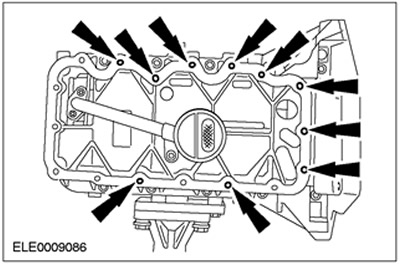
13.
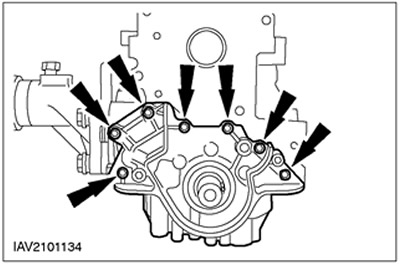
CAUTION: Sealant entering blind holes may damage the lower crankcase section.
Install ten M6 x 20mm studs in blind holes as shown.
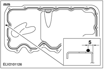
14.
NOTE: Fix the oil pan within ten minutes after applying the sealant.
Apply a 3 mm thick bead of sealant to the mating surface of the oil pan.
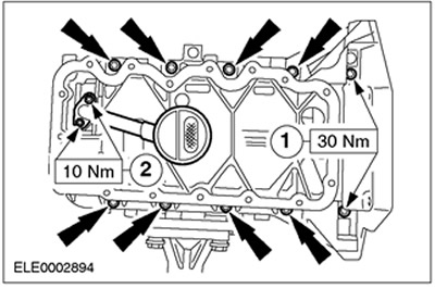
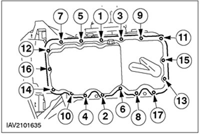
15.
NOTE: After contact with the body of the lower section of the crankcase, it is not allowed to remove the oil pan.
Install the oil pan.
- Remove the pins.
- Install and tighten the bolts in the sequence shown, working in two steps.
- 1st stage: 6 Nm
- 2nd stage: 10 Nm
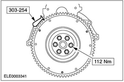
16.
NOTE: Install new flywheel mounting bolts.
NOTE: Remove any remaining thread locking compound from the threaded holes.
Using the special tool, install the flywheel.
17. Install the driven and pressure plates of the clutch. See Section 303-01A / 303-01B / 303-01C / 303-01D / 303-01E for more information.
18.
NOTE: Install a new cylinder head gasket.
NOTE: Install the cylinder head bolts without oil.
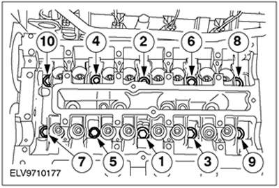
NOTE: Tighten the cylinder head bolts in three stages, working in the sequence shown.
Install the cylinder head.
- 1st stage: 20 Nm
- 2nd stage: 40 Nm
- 1st stage: 90 degrees
19. Lubricate the valve lifters with engine oil and install them in the correct order.
20. Rotate the crankshaft to approximately 60 degrees BTDC.
21. Install the camshafts so that none of the cams is in the full lift position.
22. Apply engine oil to the camshafts and camshaft bearing caps and install them in place.
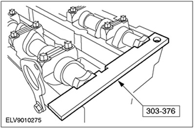
23.
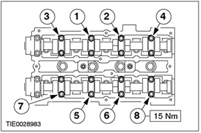
NOTE: Working in several steps, evenly tighten the camshaft bearing cap bolts in the sequence shown, tightening the bolts half a turn per step.
Install the camshafts. Tighten the bolts in the sequence shown.
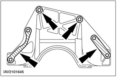
24.
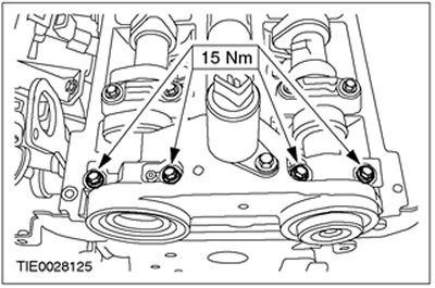
NOTE: Install a new oil feed flange oil seal.
Apply sealant to the marked areas on the oil supply flange.
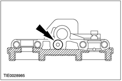
25. Install the oil supply flange.
26. Install the exhaust camshaft oil seal.
- Lubricate the camshaft and the sealing lip of the oil seal with engine oil.
- Install new oil seals using the special tool, washer and M10x70 bolt.
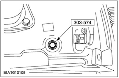
27. Rotate the crankshaft to top dead center for cylinder No.1.
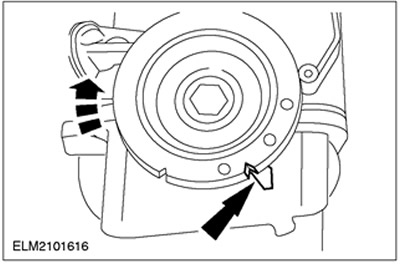
28.
NOTE: Cylinders #1 and #4 are at top dead center when the key is facing the piston.
Remove the plug and use the special tool to align the crankshaft to top dead center.

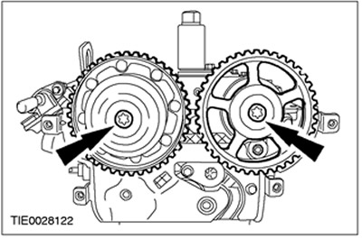
29. Turn the camshafts to the ignition point on cylinder No. 1 and insert the special tool into the camshafts.
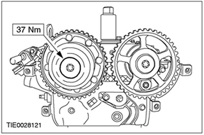
30.
NOTE: Do not fully tighten the camshaft pulley mounting bolts at this stage.
Install the camshaft pulleys.
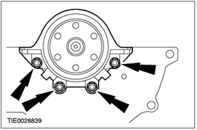
31. Install a new water pump gasket by bending the tabs.
- 1.Reinstall the gasket.
- 2.Fix the pad by bending the tabs.
32.
CAUTION: Do not kink the timing belt (do not bend the timing belt with more than 35 mm diameter).
CAUTION: Do not turn the crankshaft, make sure it is still against the torque setting pin.
NOTE: When installing the timing belt, do not allow the tab on the timing belt tensioner to go inside the sheet metal cover.
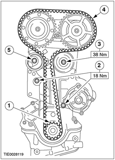
Position the new timing belt.
- 1.Install the crankshaft pulley with thrust washer on the crankshaft.
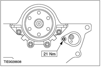
- 2.Install the water pump.
- 3.Install the upper intermediate pulley.
- 4. Starting at the crankshaft timing belt pulley and working in a counterclockwise direction, position the timing belt while keeping the belt taut.
- 5.Fix the timing belt tensioner and tighten the bolt five turns.
33.
CAUTION: Incorrect timing belt tension results in incorrect distribution of valve actuation moments.
Pre-tension the timing belt.
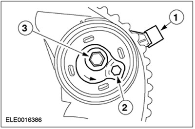
- 1.Turn the adjusting tab of the tensioner counterclockwise and insert the adjusting tab into the slot in the rear timing cover.
- 2. Position the hex keyway in the tensioner shim at the 4 o'clock position.
- 3. Using a 6mm Allen wrench, tighten the bolt just enough to firmly seat the tensioner on the rear timing cover, but still allow the tensioner shim to rotate.
34.
CAUTION: Tighten the timing chain by working counterclockwise.
Using a hex wrench, turn the shim counterclockwise until the notch in the arrow is centered over the reference line on the setting foot (during adjustment, the hand moves clockwise).
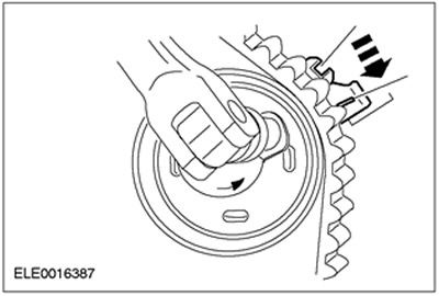
35. While holding the shim in position, tighten the bolt.
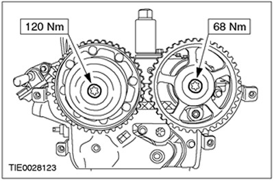
36.
NOTE: Hold the camshafts with an open end hex wrench to prevent them from turning.
Tighten the camshaft pulley bolts.
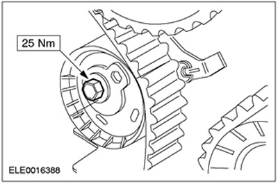
37.
NOTE: Hold the camshaft with an open end hex wrench to prevent it from turning.
Install the intake camshaft pulley cap.
38. Remove the special tool.
39. Remove the special tool.

40.
NOTE: Rotate the engine two revolutions in the direction of normal crankshaft rotation.
Check the valve timing by installing special tools, and correct the alignment if necessary.
- Screw in the special tool 303-574 and make sure that the crankshaft is supported by the special tool.
- Insert special tool 303-376 into the camshafts. If necessary, loosen the timing pulleys and correct the camshaft alignment.
- Remove special tools.
41. Install the plug.
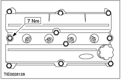
42. Install the valve cover.
43.
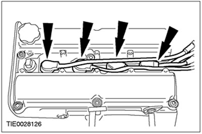
CAUTION: Use a blunt object (plastic clamp) to apply silicone grease to prevent damage to spark plug electrical connectors.
CAUTION: Press on the spark plug electrical connectors, keeping them in line with the spark plugs.
NOTE: Apply 5 to 10 mm of silicone grease to the inside of the spark plug electrical connectors.
Connect the spark plug electrical connectors. Push the spark plug electrical connectors until they click into place.
44.
NOTE: Check top cover gasket installation and adjust gasket if necessary.
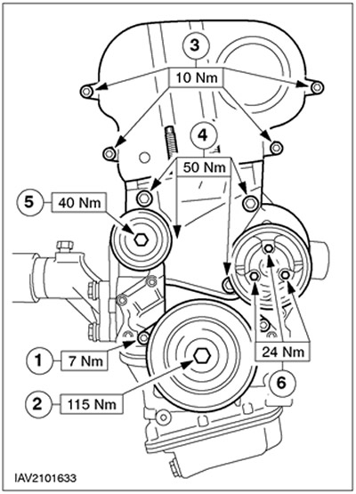
Install the timing belt covers and pulleys.
- 1.Bottom cover
- 2.Crankshaft pulley
- 3.Top cover
- 4. Bracket front engine mount.
- 5.Intermediate pulley drive belt
- 6.Water pump pulley
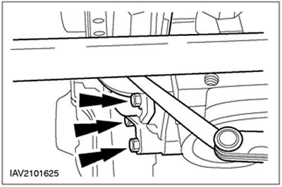
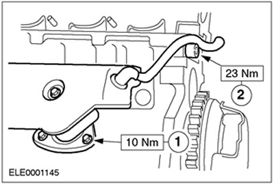
45. Connect the forced crankcase ventilation hose. Use a new seal.
- 1.Three bolts
- 2.One bolt
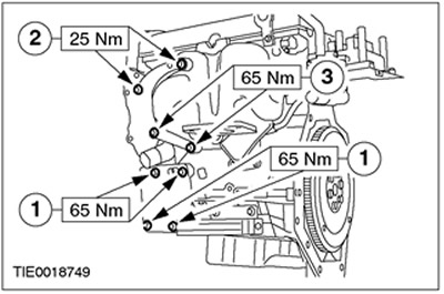
46. Connect the auxiliary elements located on the exhaust side.
- 1. Bracket for air conditioning compressor.
- 2. Power steering pump bracket.
- 3. Bracket for connecting the power steering pump to the cylinder block.
47. Install the oil cooler.
48. Attach the engine to the engine lifting eyes on the hoist and remove it from the assembly stand. Lower the engine on the assembly stand and leave it attached to the hoist.
49.
NOTE: Coat the oil filter seal with engine oil.
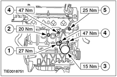
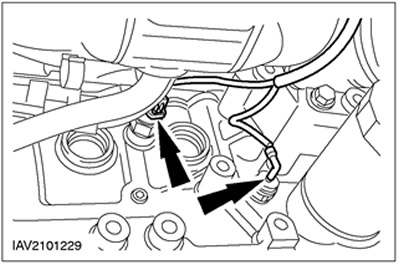
Connect the auxiliary elements located on the inlet side.
- 1. Oil pressure switch
- 2.Knock sensor (KS)
- 3.Install a new oil filter.
- 4. Generator bracket fixed on the cylinder block
- 5. Generator bracket mounted on the cylinder head
50. Raise and support the vehicle. See Section 100-02 for more information.
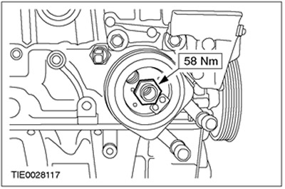
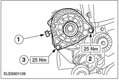
51. Install the generator.
- 1.Tighten the bolt.
- 2.Tighten the bolt.
- 3. Connect the positive wire.
52. Connect the electrical connectors for the oil pressure switch and the KS sensor.
Visitor comments