|
STATES |
DETAILS/RESULTS/ACTIONS |
|
E1: DETERMINING THE CONDITIONS UNDER WHICH A FAILURE OCCURRS |
|
|
1Enter the ON position. |
|
|
2Cycle the heater fan switch through all positions. |
|
|
• Heater blower motor not working at all speed settings? |
|
|
→ Yes |
|
|
→ No |
|
|
E2: CHECKING FUSE F64 |
|
|
1Enter the OFF position. |
|
|
2CHECK Fuse F64 (BJB). |
|
|
• Is the fuse good? |
|
|
→ Yes |
|
|
→ No |
|
|
REPLACE fuse F64 (40A). CHECK the system for proper operation. If the fuse blows again, LOCATE and REPAIR the short to ground using the wiring diagrams. |
|
|
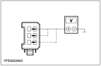
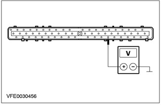
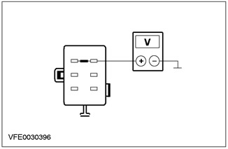
E3: CHECKING THE VOLTAGE IN FUSE F64 |
|
|
1Connect Fuse F64 (BJB). |
|
|
2Enter the ON position. |
|
|
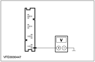
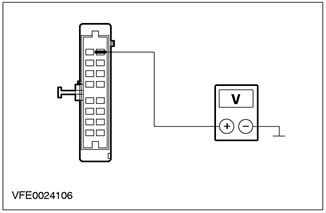
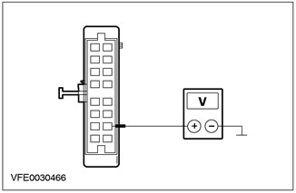
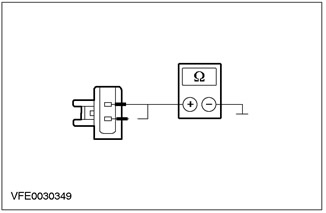
3Check the voltage in the electrical circuit between fuse F64 (40 A) and ground. |
|
|
• Is battery voltage registered? |
|
|
→ Yes |
|
|
→ No |
|
|
RESTORE power to fuse F64 using the wiring diagrams. CHECK that the system is operating correctly |
|
|
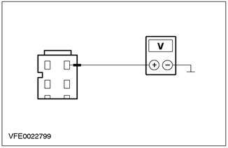
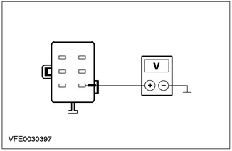
E4: CHECKING THE VOLTAGE IN THE HEATER FAN MOTOR |
|
|
1Enter the OFF position. |
|
|
2Disconnect C789 heater blower motor. |
|
|
3Enter the ON position. |
|
|
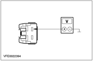
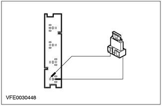
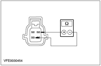
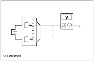
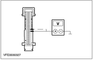
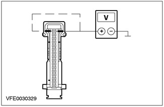
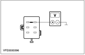
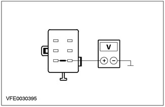
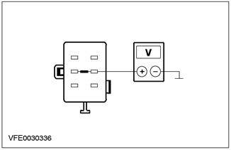
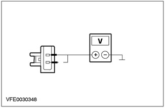
4Measure the voltage between pin 1 of the heater blower motor connector C789, circuit 15-FA18 (green/orange), wiring harness side, and ground. |
|
• Is battery voltage registered? |
|
|
→ Yes |
|
|
→ No |
|
|
LOCATE and REPAIR the open in the electrical circuit between the heater blower motor and the F64 fuse electrode using the wiring diagrams. CHECK the correct operation of the system |
|
|
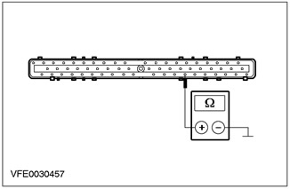
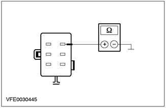
E5: CHECKING THE ELECTRICAL GROUND CIRCUIT OF THE HEATER ELECTRIC FAN |
|
|
1Enter the OFF position. |
|
|
2Set the heater fan switch to "maximum". |
|
|
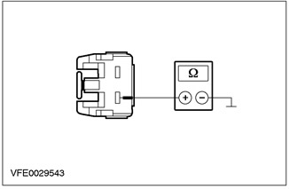
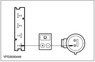
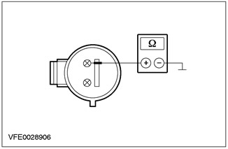
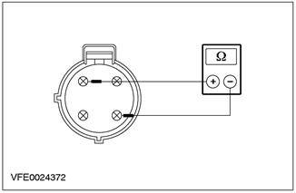
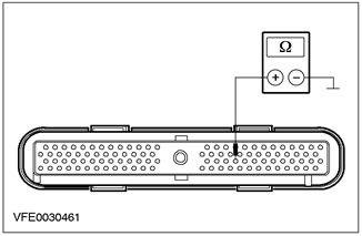
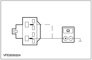
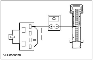
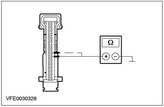
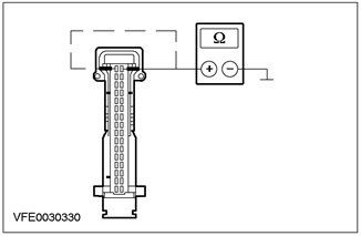
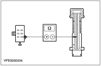
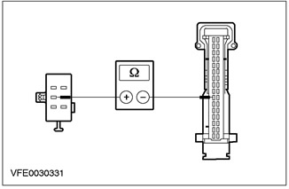
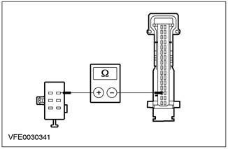
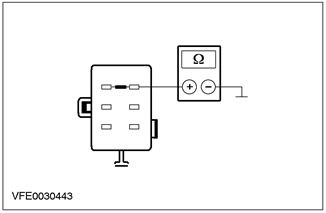
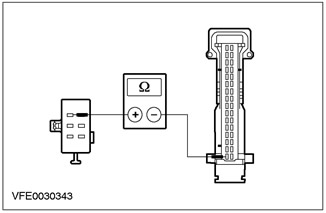
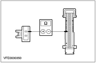
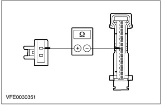
3Measure the resistance between pin 2 of the C789 heater blower motor connector, circuit 31S-FA18 (black/red), wiring harness side, and ground. |
|
• Is the measured resistance less than 2 ohms? |
|
|
→ Yes |
|
|
REPLACE the heater blower. CHECK the system for proper operation |
|
|
→ No |
|
|
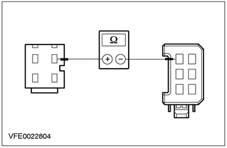
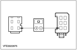
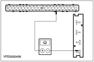
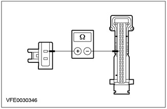
E6: CHECKING THE ELECTRICAL CIRCUIT BETWEEN THE HEATER FAN MOTOR AND THE HEATER FAN SWITCH |
|
|
1Disconnect C469 heater fan switch. |
|

|
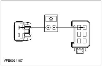
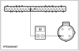
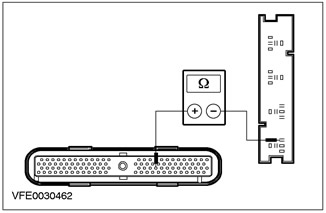
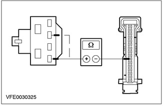
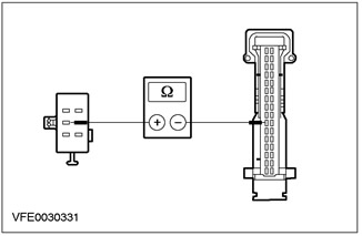
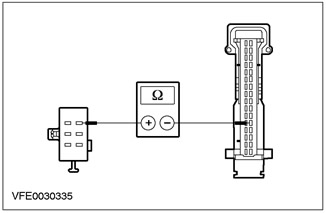
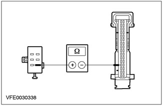
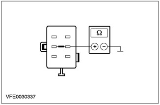
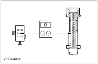
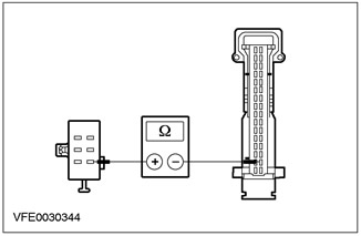
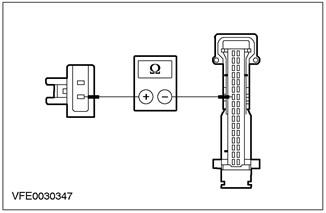
2Measure the resistance between pin 2 C789 of the heater blower motor, circuit 31S-FA18 (BK/RED), wiring harness side and pin 6 C469 of the heater blower switch, circuit 31S-FA33 (BK/ORN), wiring harness side. |
|
• Is the measured resistance less than 2 ohms? |
|
|
→ Yes |
|
|
→ No |
|
|
LOCATE and REPAIR the open in the 31S-FA18 (black/red) circuit between the heater blower motor and solder joint S24 using the wiring diagrams. CHECK the system for proper operation |
|
|
E7: CHECKING THE HEATER FAN SWITCH GROUND CIRCUIT |
|
|
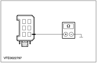
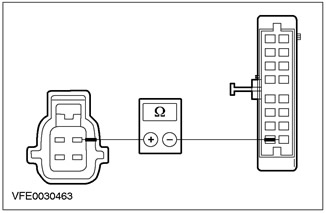
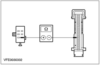
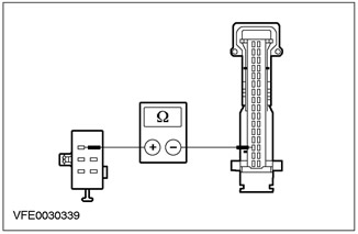
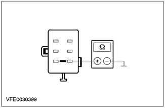
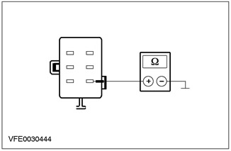
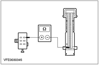
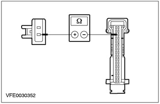
1Measure the resistance between pin 2 of the heater blower switch connector C469, circuit 31-FA25 (black), wiring harness side and ground. |
|
• Is the measured resistance less than 2 ohms? |
|
|
→ Yes |
|
|
REPLACE the heater fan switch. CHECK the system for proper operation |
|
|
→ No |
|
|
LOCATE and REPAIR the open in the electrical circuit between the heater blower switch and ground point G14 using the wiring diagrams. CHECK the system for proper operation |
|
|
E8: DETERMINING THE CONDITIONS UNDER WHICH A FAULT OCCURRS |
|
|
1Set the heater fan switch to "maximum". |
|
|
• Heater fan motor not working? |
|
|
→ Yes |
|
|
→ No |
|
|
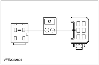
E9: CHECKING THE ELECTRICAL CIRCUIT BETWEEN THE HEATER FAN MOTOR AND THE HEATER FAN SWITCH |
|
|
1Enter the OFF position. |
|
|
2Disconnect C469 heater fan switch. |
|
|
3Disconnect C789 heater blower motor. |
|
|
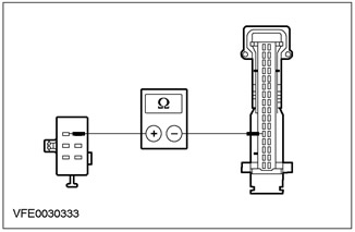
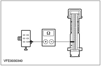
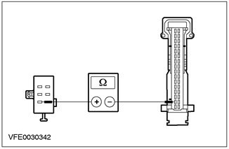
4Measure the resistance between pin 2 C789 of the heater blower motor, circuit 31S-FA18 (BK/RED), wiring harness side and pin 6 C469 of the heater blower switch, circuit 31S-FA33 (BK/ORN), wiring harness side. |
|
• Is the measured resistance less than 2 ohms? |
|
|
→ Yes |
|
|
REPLACE the heater fan switch. CHECK the system for proper operation |
|
|
→ No |
|
|
LOCATE and REPAIR the open in the 31S-FA33 (Black/Orange) circuit between solder joint S24 and the heater blower switch using the wiring diagrams. CHECK for proper system operation |
|
|
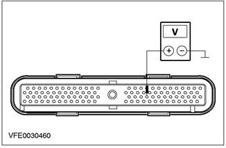
E10: CHECKING THE HEATER FAN SWITCH |
|
|
1Enter the OFF position. |
|
|
2Disconnect C469 heater fan switch. |
|
|
3Enter the ON position. |
|
|
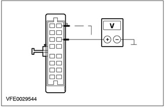
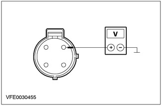
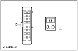
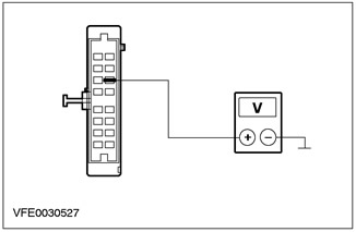
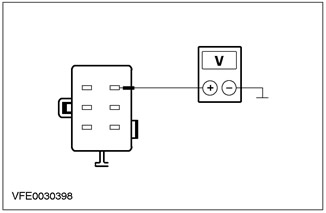
4Measure the voltage between pin 5 of the heater blower switch connector C469, circuit 31S-FA32 (BLK/BU), wiring harness side and ground. |
|
5Measure the voltage between pin 3 of the heater blower switch connector C469, circuit 31S-FA31 (BK/YE), wiring harness side and ground. |
|
|
6Measure the voltage between pin 1 of the heater blower switch connector C469, circuit 31S-FA30 (BK/WH), wiring harness side and ground. |
|
|
• Is battery voltage registered in all cases? |
|
|
→ Yes |
|
|
REPLACE the heater fan switch. CHECK the system for proper operation |
|
|
→ No |
|
|
E11: CHECKING THE ELECTRICAL CIRCUIT BETWEEN THE HEATER FAN MOTOR AND THE HEATER FAN VARIABLE RESISTOR |
|
|
1Enter the OFF position. |
|
|
2Disconnect C470 heater blower variable resistor. |
|
|
3Enter the ON position. |
|
|
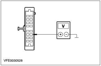
4Measure the voltage between pin 1 of the C470 plug of the heater blower variable resistor, circuit 31S-FA33 (black/orange), wiring harness side, and ground. |
|
• Is battery voltage registered? |
|
|
→ Yes |
|
|
→ No |
|
|
LOCATE and REPAIR the open in the electrical circuit between solder joint S24 and the heater blower variable resistor using the wiring diagrams. CHECK the system for proper operation |
|
|
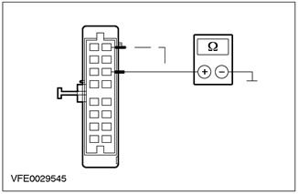
E12: CHECKING THE ELECTRICAL CIRCUIT BETWEEN THE HEATER FAN VARIABLE RESISTOR AND THE HEATER FAN SWITCH |
|
|
1Enter the OFF position. |
|
|
2Measure the resistance between pin 4 of connector C470 of the heater blower variable resistor, circuit 31S-FA32 (BLK/BU), wiring harness side and pin 5 of connector C469 of the heater blower switch, circuit 31S-FA32 (BLK/BU), wiring harness side. |
|
• Is the measured resistance less than 2 ohms? |
|
|
→ Yes |
|
|
→ No |
|
|
LOCATE and REPAIR the open in the 31S-FA32 (BLK/BLK) circuit between the heater blower variable resistor and the heater blower switch using the wiring diagrams. CHECK for proper system operation |
|
|
E13: CHECKING THE ELECTRICAL CIRCUIT BETWEEN THE HEATER FAN VARIABLE RESISTOR AND THE HEATER FAN SWITCH |
|
|
1Measure the resistance between pin 2 of the heater blower variable resistor connector C470, circuit 31S-FA31 (BK/YE), wiring harness side and pin 3 of the heater blower switch connector C469, circuit 31S-FA31 (BK/YE), wiring harness side. |
|
• Is the measured resistance less than 2 ohms? |
|
|
→ Yes |
|
|
→ No |
|
|
LOCATE and REPAIR the open in the 31S-FA31 (BK/YEL) circuit between the heater blower variable resistor and the heater blower switch using the wiring diagrams. CHECK for proper system operation |
|
|
E14: CHECKING THE ELECTRICAL CIRCUIT BETWEEN THE HEATER FAN VARIABLE RESISTOR AND THE HEATER FAN SWITCH |
|
|
1Measure the resistance between pin 3 of connector C470 of the heater blower variable resistor, circuit 31S-FA30 (BK/WH), wiring harness side and pin 1 of connector C469 of the heater blower switch, circuit 31S-FA30 (BK/WH), wiring harness side. |
|
• Is the measured resistance less than 2 ohms? |
|
|
→ Yes |
|
|
REPLACE the heater fan variable resistor. CHECK the system for proper operation |
|
|
→ No |
|
|
LOCATE and REPAIR the open in circuit 31S-FA30 (B/W) between the heater blower variable resistor and the heater blower switch using the wiring diagrams. CHECK for proper system operation |
|
PINPOINT TEST F: HEATER FAN CONTINUOUSLY RUNS (NON-EATC VEHICLES ONLY)
|
STATES |
DETAILS/RESULTS/ACTIONS |
|
F1: CHECKING THE HEATER FAN SWITCH |
|
|
1Enter the OFF position. |
|
|
2Disconnect C469 heater fan switch. |
|
|
3Enter the ON position. |
|
|
• Does the heater fan motor run continuously? |
|
|
→ Yes |
|
|
Go to F2 |
|
|
→ No |
|
|
REPLACE the heater fan switch. CHECK the system for proper operation |
|
|
F2: CHECKING ELECTRICAL CIRCUITS IN THE HEATER FAN VARIABLE RESISTOR |
|
|
1Enter the OFF position. |
|
|
2Disconnect C470 heater blower variable resistor. |
|
|
3Enter the ON position. |
|
|
• Does the heater fan motor run continuously? |
|
|
→ Yes |
|
|
CHECK all electrical circuits connected to solder joint S24 for shorts to ground using the wiring diagrams and REPAIR any short(s) found. CHECK proper system operation |
|
|
→ No |
|
|
CHECK all electrical circuits between the heater blower variable resistor and the heater blower switch for shorts to ground using the wiring diagrams and REPAIR any short(s) found. CHECK the system for proper operation |
|
PINPOINT TEST G: AIR RECIRCULATION FLAP MALFUNCTIONING (NON-EATC VEHICLES ONLY)
|
STATES |
DETAILS/RESULTS/ACTIONS |
|
NOTE:The air recirculation flap is driven by a DC motor. After pressing the recirculation button, this DC motor is activated by the heater control module for a maximum of 7 seconds. The opening and closing of the air recirculation flap is performed by changing the polarity of the supplied voltage. |
|
|
NOTE:If the air distribution control switch is set to the defog/defrost position, the air recirculation mode cannot be switched on. |
|
|
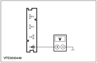
G1: CHECKING THE VOLTAGE IN THE AIR RECIRCULATION FLAP POSITIONING MOTOR CIRCUIT |
|
|
1Enter the OFF position. |
|
|
2Disconnect C538 air recirculation flap positioning motor. |
|
|
3Enter the ON position. |
|
|
4Measure the voltage between pins 2 and 4 of the air recirculation flap positioning motor connector C538, on the wiring harness side. |
|
|
5During the measurement process, press the air recirculation button several times. |
|
|
• Is the voltage registered at about 11 V with alternating polarity? |
|
|
→ Yes |
|
|
CHECK the air recirculation flap for freedom of movement and proper operation. If the air recirculation flap is mechanically OK, REPLACE the air recirculation flap positioning motor. CHECK the system for proper operation |
|
|
→ No |
|
|
Go to G2 |
|
|
G2: CHECKING THE ELECTRICAL CIRCUIT BETWEEN THE HEATER CONTROL MODULE AND THE AIR RECIRCULATION FLAP POSITIONING MOTOR |
|
|
1Enter the OFF position. |
|
|
2Disconnect the C380 Heater Control Module. |
|
|
3Measure the resistance between pin 16 of the heater control module connector C380, circuit 33-FA76 (YE/BU), wiring harness side and pin 2 of the recirculated air flap servo motor connector C538, circuit 33-FA76 (YE/BU) (RHD vehicles: circuit 32-FA76 (WH/BU)), wiring harness side. |
|
|
• Is the measured resistance less than 2 ohms? |
|
|
→ Yes |
|
|
Go to G3 |
|
|
→ No |
|
|
LOCATE and REPAIR the open in circuit 33-FA76 (YE/BL) (RHD vehicles: circuit 32-FA76 (WH/BL)) between the heater control module and the recirculated air flap positioning motor using the Wiring Diagrams. CHECK for proper system operation |
|
|
G3: CHECKING THE ELECTRICAL CIRCUIT BETWEEN THE HEATER CONTROL MODULE AND THE AIR RECIRCULATION FLAP POSITIONING MOTOR |
|
|
1Measure the resistance between pin 14 of the heater control module connector C380, circuit 32-FA76 (WH/BU), wiring harness side and pin 4 of the recirculated air flap servo motor connector C538, circuit 32-FA76 (WH/BU) (right-hand drive vehicles: circuit 33-FA76 (YE/BU)), wiring harness side. |
|
|
• Is the measured resistance less than 2 ohms? |
|
|
→ Yes |
|
|
Go to G4 |
|
|
→ No |
|
|
LOCATE and REPAIR the open in circuit 32-FA76 (white/blue) (right-hand drive vehicles: circuit 33-FA76 (yellow/blue)) between the heater control module and the recirculated air flap positioning motor using the Wiring Diagrams. CHECK for proper system operation |
|
|
G4: CHECK THE ELECTRICAL CIRCUIT BETWEEN THE HEATER CONTROL MODULE AND THE AIR RECIRCULATION FLAP POSITIONING MOTOR FOR A SHORT TO BATTERY + |
|
|
1Enter the ON position. |
|
|
2Measure the voltage between pin 14 of the heater control module connector C380, circuit 32-FA76 (blue/white), wiring harness side, and ground. |
|
3Measure the voltage between pin 16 of the heater control module connector C380, circuit 33-FA76 (yellow/blue), wiring harness side, and ground. |
|
|
• Is voltage registered? |
|
|
→ Yes |
|
|
LOCATE and REPAIR the short to battery in circuit 32-FA76 (WH/BL) or 33-FA76 (YEL/BL) between the heater control module and the recirculated air flap positioning motor using the Wiring Diagrams. CHECK for proper system operation |
|
|
→ No |
|
|
Go to G5 |
|
|
G5: CHECK THE ELECTRICAL CIRCUIT BETWEEN THE HEATER CONTROL MODULE AND THE AIR RECIRCULATION FLAP POSITIONING MOTOR FOR A SHORT CIRCUIT "MASS" |
|
|
1Enter the OFF position. |
|
|
2Measure the resistance between pin 14 of the heater control module connector C380, circuit 32-FA76 (blue/white), wiring harness side, and ground. |
|
3Measure the resistance between pin 16 of the heater control module connector C380, circuit 33-FA76 (yellow/blue), wiring harness side, and ground. |
|
|
• Is the measured resistance greater than 10 kOhm in both cases? |
|
|
→ Yes |
|
|
CHECK and REPLACE if necessary the heater control module. CHECK the system for proper operation |
|
|
→ No |
|
|
LOCATE and REPAIR the short to ground in circuit 32-FA76 (WH/BU) or 33-FA76 (YE/BU) between the heater control module and the recirculated air flap positioning motor using the Wiring Diagrams. CHECK for proper system operation |
|
PINPOINT TEST H: AIR CONDITIONING SYSTEM NOT WORKING (HEATER FAN OK)
|
STATES |
DETAILS/RESULTS/ACTIONS |
|
H1: REQUEST WDS FAULT CODES |
|
|
1Enter the OFF position. |
|
|
2Connect the diagnostic tool. |
|
|
3Enter the START position. |
|
|
4Request DTCs - Run the Engine Management System diagnostic routine using WDS. |
|
|
• Are there any fault codes present? |
|
|
→ Yes |
|
|
PERFORM the necessary troubleshooting steps as directed by WDS. CHECK that the system is operating correctly |
|
|
→ No |
|
|
Go to H2 |
|
|
H2: CHECKING FUSE F15 |
|
|
1Enter the OFF position. |
|
|
2CHECK Fuse F15 (BJB). |
|
|
• Is the fuse good? |
|
|
→ Yes |
|
|
Go to H3 |
|
|
→ No |
|
|
REPLACE fuse F15 (10A). If the fuse blows again after turning on the A/C system, CHECK the A/C compressor clutch diode and REPLACE it if necessary. If the diode is OK, LOCATE and REPAIR the short to ground using the wiring diagrams. CHECK the system for proper operation |
|
|
H3: CHECKING THE VOLTAGE IN FUSE F15 |
|
|
1Connect Fuse F15 (BJB). |
|
|
2Check the voltage in the electrical circuit between fuse F15 (10 A) and ground. |
|
|
• Is battery voltage registered? |
|
|
→ Yes |
|
|
Non-EATC vehicles: Go to H4 |
|
|
EATC Cars: Go to H8 |
|
|
→ No |
|
|
RESTORE power to fuse F15 using the wiring diagrams. CHECK that the system is operating correctly |
|
|
H4: CHECKING FUSE F36 |
|
|
1CHECK Fuse F36 (CJB). |
|
|
• Is the fuse good? |
|
|
→ Yes |
|
|
Go to H5 |
|
|
→ No |
|
|
REPLACE fuse F36 (7.5A). If the fuse blows again, LOCATE and REPAIR the short to ground using the wiring diagrams. CHECK the system for proper operation. |
|
|
H5: CHECKING THE VOLTAGE IN FUSE F36 |
|
|
1Connect Fuse F36 (CJB). |
|
|
2Check the voltage in the electrical circuit between fuse F36 (7.5 A) and ground. |
|
|
• Is battery voltage registered? |
|
|
→ Yes |
|
|
Go to H6 |
|
|
→ No |
|
|
RESTORE power to fuse F36 using the wiring diagrams. CHECK that the system is operating correctly. |
|
|
H6: CHECKING FUSE F45 |
|
|
1CHECK Fuse F45 (CJB). |
|
|
• Is the fuse good? |
|
|
→ Yes |
|
|
Go to H7 |
|
|
→ No |
|
|
REPLACE fuse F45 (7.5A). If the fuse blows again, LOCATE and REPAIR the short to ground using the wiring diagrams. CHECK the system for proper operation. |
|
|
H7: CHECKING THE VOLTAGE IN FUSE F45 |
|
|
1Connect Fuse F45 (CJB). |
|
|
2Enter the ON position. |
|
|
3Check the voltage in the electrical circuit between fuse F45 (7.5 A) and ground. |
|
|
• Is battery voltage registered? |
|
|
→ Yes |
|
|
Go to H8 |
|
|
→ No |
|
|
RESTORE power to fuse F45 using the wiring diagrams. CHECK that the system is operating correctly. |
|
|
H8: CHECKING THE SUPPLY VOLTAGE AT THE A/C WOT RELAY |
|
|
1Enter the OFF position. |
|
|
2Disconnect C1011 A/C WOT Relay (BJB). |
|
|
3Measure the voltage between A/C WOT relay connector C1011 pin 3, circuit 15-FA38 (Green/Red), harness side and ground. |
|
• Is battery voltage registered? |
|
|
→ Yes |
|
|
Go to H9 |
|
|
→ No |
|
|
LOCATE and REPAIR the open in the 15-FA38 (Green/Red) circuit between fuse F15 and the A/C WOT relay using the Wiring Diagrams. CHECK for proper system operation. |
|
|
H9: CHECKING CONTROL VOLTAGE AT A/C WOT RELAY |
|
|
1Enter the START position. |
|
|
2Measure the voltage between A/C WOT relay connector C1011 pin 1, circuit 15-FA11 (GREEN/YEL), harness side and ground. |
|
• Is battery voltage registered? |
|
|
→ Yes |
|
|
Go to H10 |
|
|
→ No |
|
|
LOCATE and REPAIR the open in the 15-FA11 (GREEN/YELLOW) circuit between solder joint S117 and the A/C WOT relay using the Wiring Diagrams. CHECK for proper system operation. |
|
|
H10: CHECK A/C COMPRESSOR CLUTCH ELECTRICAL CIRCUIT |
|
|
1Enter the OFF position. |
|
|
2Use a fused test lead (10A) to short pins 3 and 5 of the A/C WOT relay connector C1011, harness side. |
|
3Enter the START position. |
|
|
4Check the operation of the A/C compressor clutch. |
|
|
• Is the A/C compressor clutch working? |
|
|
→ Yes |
|
|
Go to H13 |
|
|
→ No |
|
|
Go to H11 |
|
|
H11: CHECK THE ELECTRICAL CIRCUIT BETWEEN A/C WOT RELAY AND A/C COMPRESSOR CLUTCH FOR OPEN |
|
|
1Enter the OFF position. |
|
|
2Disconnect C952 A/C compressor clutch. |
|
|
3Measure the resistance between A/C WOT relay connector C1011 pin 5, harness side and A/C compressor clutch connector C952 pin 1, circuit 15S-FA6 (GN/YE), harness side. |
|
• Is the measured resistance less than 2 ohms? |
|
|
→ Yes |
|
|
Go to H12 |
|
|
→ No |
|
|
LOCATE and REPAIR the open in the electrical circuit between the A/C WOT relay and the A/C compressor clutch using the wiring diagrams. CHECK for proper system operation. |
|
|
H12: CHECKING THE A/C COMPRESSOR CLUTCH GROUND CIRCUIT |
|
|
1Measure the resistance between A/C compressor clutch connector C952 pin 2, circuit 31-FA6 (Black), wiring harness side and ground. |
|
• Is the measured resistance less than 2 ohms? |
|
|
→ Yes |
|
|
REPLACE the A/C compressor clutch. CHECK the system for proper operation. |
|
|
→ No |
|
|
LOCATE and REPAIR the open in the electrical circuit between the A/C compressor clutch and ground point G56 using the wiring diagrams. CHECK for proper system operation. |
|
|
H13: CHECKING THE A/C WOT RELAY GROUND CIRCUIT |
|
|
1Turn on the heater fan. |
|
|
2Turn on the air conditioning system. |
|
|
CAUTION: When performing the following test, it is necessary to use a test lamp with a rated voltage of 12 V and a rated power of 1.2 W. Otherwise, the PCM may be damaged or the test may give incorrect results. 3To check the voltage between pins 1 and 2 of the A/C WOT relay connector C1011, use a test light (12V, 1.2W). |
|
• Is the indicator light on? |
|
|
→ Yes |
|
|
REPLACE the A/C WOT relay. CHECK the system for proper operation. |
|
|
→ No |
|
|
Go to H14 |
|
|
H14: CHECKING THE AMOUNT OF REFRIGERANT |
|
|
1Enter the OFF position. |
|
|
2Check the amount of refrigerant in the system. REFER to 346202 in this section. |
|
|
• Does the amount of refrigerant in the system comply with the manufacturer's specifications? |
|
|
→ Yes |
|
|
Go to H15 |
|
|
→ No |
|
|
CHARGE the system with the correct amount of refrigerant. CHECK the system for leaks and CHECK the system operation. |
|
|
H15: CHECK CIRCUIT BETWEEN HEATER CONTROL MODULE OR EATC MODULE AND PCM FOR SHORT TO BATTERY + |
|
|
1Disconnect C380 Heater Control Module or EATC Module. |
|
|
2Disconnect C416 PCM (or C415 with 104-pin EEC V). |
|
|
3Enter the ON position. |
|
|
4Measure the voltage between pin 9 of the heater control module or EATC module connector C380, circuit 15S-FA38 (green/red), wiring harness side and ground. |
|
• Is voltage registered? |
|
|
→ Yes |
|
|
LOCATE and REPAIR the short to battery voltage in the 15S-FA38 (GN/RED), 15S-FA 17 (GN/OR), or 15S-RE 8 (GN/YE) circuit between the heater control module and the PCM using the Wiring Diagrams. CHECK for proper system operation. |
|
|
→ No |
|
|
Go to H16 |
|
|
H16: CHECK THE ELECTRICAL CIRCUIT BETWEEN THE HEATER CONTROL MODULE OR EATC MODULE AND PCM FOR SHORT CIRCUITS "MASS" |
|
|
1Enter the OFF position. |
|
|
2Measure the resistance between pin 8 of the heater control module or EATC module connector C380, circuit 15S-FA38 (green/red), wiring harness side and ground. |
|
• Is the measured resistance less than 10,000 ohms? |
|
|
→ Yes |
|
|
LOCATE and REPAIR the short to ground in circuit 15S-FA38 (GN/RED), 15S-FA 17 (GN/OG), or 15S-RE 8 (GN/YE) between the heater control module or EATC module and the PCM using the Wiring Diagrams. CHECK for proper system operation. |
|
|
→ No |
|
|
Go to H17 |
|
|
H17: CHECKING THE VOLTAGE IN THE DUAL PRESSURE SWITCH |
|
|
1Connect C380 Heater Control Module or EATC Module. |
|
|
2Connect C416 PCM (or C415 with 104-pin EEC V). |
|
|
3Disconnect Dual Pressure Switch C882. |
|
|
4Enter the START position. |
|
|
5Turn on the heater fan. |
|
|
6Turn on the air conditioning system. |
|
|
7Measure the voltage between pin 1 of the dual relay connector C882, circuit 15S-FA38 (green/red), wiring harness side, and ground. |
|
• Is battery voltage registered? |
|
|
→ Yes |
|
|
Go to H18 |
|
|
→ No |
|
|
Go to H29 |
|
|
H18: CHECKING THE DUAL PRESSURE SWITCH |
|
|
1Enter the OFF position. |
|
|
2Measure the resistance between pins 1 and 4 of the C882 dual pressure switch connector, element side. |
|
• Is the measured resistance less than 2 ohms? |
|
|
→ Yes |
|
|
Go to H19 |
|
|
→ No |
|
|
REPLACE the dual pressure switch. CHECK the system for proper operation. |
|
|
H19: CHECKING VOLTAGE AT A/C COMPRESSOR SWITCH |
|
|
1Connect C882 dual pressure switch. |
|
|
2Disconnect C692 A/C Compressor Switch. |
|
|
3Enter the START position. |
|
|
4Turn on the heater fan. |
|
|
5Turn on the air conditioning system. |
|
|
6Measure the voltage between A/C compressor switch connector C692 pin 1, circuit 15S-FA17 (Green/Orange), harness side and ground. |
|
• Is battery voltage registered? |
|
|
→ Yes |
|
|
Go to H20 |
|
|
→ No |
|
|
LOCATE and REPAIR the open in the 15S-FA17 (Green/Orange) circuit between the dual pressure switch and the A/C compressor switch using the wiring diagrams. CHECK for proper system operation. |
|
|
H20: CHECK A/C COMPRESSOR SWITCH |
|
|
1Enter the OFF position. |
|
|
2Measure the resistance between pins 1 and 4 of connector C692 of the air conditioning compressor switch, on the element side. |
|
• Is the measured resistance less than 2 ohms? |
|
|
→ Yes |
|
|
Vehicles with EEC V (60-pin): Go to H21 |
|
|
Vehicles with EEC V (104-pin): Go to H25 |
|
|
→ No |
|
|
Replace A/C compressor switch. CHECK system for proper operation. |
|
|
H21: CHECK FOR OPEN CIRCUIT BETWEEN A/C COMPRESSOR SWITCH AND PCM |
|
|
1Disconnect PCM C416. |
|
2Measure the resistance between PCM connector C416 pin 10, circuit 15S-RE8 (GN/YE), harness side and A/C compressor switch connector C692 pin 4, circuit 15S-RE8 (GN/YE), harness side. |
|
|
• Is the measured resistance less than 2 ohms? |
|
|
→ Yes |
|
|
Go to H22 |
|
|
→ No |
|
|
LOCATE and REPAIR the open in the 15S-RE8 (Gen/Yellow) circuit between the A/C Compressor Switch and the PCM using the Wiring Diagrams. CHECK for proper system operation. |
|
|
H22: CHECK CIRCUIT BETWEEN A/C WOT RELAY AND PCM FOR SHORT TO BATTERY + |
|
|
1Enter the ON position. |
|
|
2Measure the voltage between PCM connector C416 pin 54, circuit 31S-FA11 (BK/YE), wiring harness side and ground. |
|
• Is voltage registered? |
|
|
→ Yes |
|
|
LOCATE and REPAIR the short to battery positive in circuit 31S-FA11 (BK/YE) between the A/C WOT relay and the PCM using the Wiring Diagrams. CHECK for proper system operation. |
|
|
→ No |
|
|
Go to H23 |
|
|
H23: CHECK CIRCUIT BETWEEN A/C WOT RELAY AND PCM FOR SHORT "MASS" |
|
|
1Enter the OFF position. |
|
|
2Measure the resistance between PCM connector C416 pin 54, circuit 31S-FA11 (BK/YE), wiring harness side and ground. |
|
• Is the measured resistance less than 10,000 ohms? |
|
|
→ Yes |
|
|
LOCATE and REPAIR the short to ground in circuit 31S-FA11 (BK/YE) between A/C WOT relay and PCM using the Wiring Diagrams. CHECK for proper system operation. |
|
|
→ No |
|
|
Go to H24 |
|
|
H24: CHECK FOR OPEN CIRCUIT BETWEEN A/C WOT RELAY AND PCM |
|
|
1Measure the resistance between PCM connector C416 pin 54, circuit 31S-FA11 (BK/YE), harness side and A/C WOT relay connector C1011 pin 2, harness side. |
|
• Is the measured resistance less than 2 ohms? |
|
|
→ Yes |
|
|
CHECK and REPLACE the PCM if necessary. CHECK the system is operating correctly. |
|
|
→ No |
|
|
LOCATE and REPAIR the open in the circuit between the A/C WOT relay and the PCM using the wiring diagrams. CHECK the system for proper operation. |
|
|
H25: CHECK FOR OPEN WIRE BETWEEN A/C COMPRESSOR SWITCH AND PCM |
|
|
1Disconnect PCM C415. |
|

|
2Measure the resistance between PCM connector C415 pin 41, circuit 15S-RE8 (GN/YE), harness side and A/C compressor switch connector C692 pin 4, circuit 15S-RE8 (GN/YE), harness side. |
|
• Is the measured resistance less than 2 ohms? |
|
|
→ Yes |
|
|
Go to H26 |
|
|
→ No |
|
|
LOCATE and REPAIR the open in the 15S-RE8 (Gen/Yellow) circuit between the A/C Compressor Switch and the PCM using the Wiring Diagrams. CHECK for proper system operation. |
|
|
H26: CHECK CIRCUIT BETWEEN A/C WOT RELAY AND PCM FOR SHORT TO BATTERY + |
|
|
1Enter the ON position. |
|
|
2Measure the voltage between PCM connector C415 pin, circuit 31S-FA11 (BK/YE), harness side and ground. |
|
• Is voltage registered? |
|
|
→ Yes |
|
|
LOCATE and REPAIR the short to battery positive in circuit 31S-FA11 (BK/YE) between the A/C WOT relay and the PCM using the Wiring Diagrams. CHECK for proper system operation. |
|
|
→ No |
|
|
Go to H27 |
|
|
H27: CHECK CIRCUIT BETWEEN A/C WOT RELAY AND PCM FOR SHORT "MASS" |
|
|
1Enter the OFF position. |
|
|
2Measure the resistance between PCM connector C415 pin 69, circuit 31S-FA11 (BK/YE), wiring harness side and ground. |
|
• Is the measured resistance less than 10,000 ohms? |
|
|
→ Yes |
|
|
LOCATE and REPAIR the short to ground in circuit 31S-FA11 (BK/YE) between A/C WOT relay and PCM using the Wiring Diagrams. CHECK for proper system operation. |
|
|
→ No |
|
|
Go to H28 |
|
|
H28: CHECK FOR OPEN CIRCUIT BETWEEN A/C WOT RELAY AND PCM |
|
|
1Measure the resistance between PCM connector C415 pin 69, circuit 31S-FA11 (BK/YE), harness side and A/C WOT relay connector C1011 pin 2, harness side. |
|
• Is the measured resistance less than 2 ohms? |
|
|
→ Yes |
|
|
CHECK and REPLACE the PCM if necessary. CHECK the system is operating correctly. |
|
|
→ No |
|
|
LOCATE and REPAIR the open in the circuit between the A/C WOT relay and the PCM using the wiring diagrams. CHECK the system for proper operation. |
|
|
H29: CHECK FOR OPEN CIRCUIT BETWEEN DUAL PRESSURE SWITCH AND HEATER CONTROL MODULE OR EATC MODULE |
|
|
1Enter the OFF position. |
|
|
2Disconnect C380 Heater Control Module or EATC Module. |
|
|
3Measure the resistance between pin 1 of the dual pressure switch connector C882, circuit 15S-FA38 (GN/RED), wiring harness side and pin 9 of the heater control module or EATC module connector C380, circuit 15S-FA38 (GN/RED), wiring harness side. |
|
• Is the measured resistance less than 2 ohms? |
|
|
→ Yes |
|
|
Non-EATC vehicles: Go to H30 |
|
|
Vehicles with EATC: CHECK and if necessary REPLACE the EATC module. CHECK that the system is operating correctly. |
|
|
→ No |
|
|
LOCATE and REPAIR the open in circuit 15S-FA38 (Green/Red) between the dual pressure switch and the heater control module or EATC module using the Wiring Diagrams. CHECK for proper system operation. |
|
|
H30: CHECKING THE HEATER CONTROL MODULE GROUND CIRCUIT |
|
|
1Measure the resistance between pin 12 of the heater control module connector C380, circuit 91-FA13 (black/orange), wiring harness side, and ground. |
|
• Is the measured resistance less than 2 ohms? |
|
|
→ Yes |
|
|
Go to H31 |
|
|
→ No |
|
|
LOCATE and REPAIR the open in the electrical circuit between the heater control module and ground point G41 using the wiring diagrams. CHECK for proper system operation. |
|
|
H31: CHECKING VOLTAGE IN THE HEATER CONTROL MODULE |
|
|
1Measure the voltage between pin 8 of the heater control module connector C380, on the wiring harness side, and ground. |
|
• Is battery voltage registered? |
|
|
→ Yes |
|
|
Go to H32 |
|
|
→ No |
|
|
LOCATE and REPAIR the open in the electrical circuit between the heater control module and fuse F36 using the wiring diagrams. CHECK the system for proper operation. |
|
|
H32: CHECKING VOLTAGE IN THE HEATER CONTROL MODULE |
|
|
1Enter the ON position. |
|

|
2Measure the voltage between pin 10 of the heater control module connector C380, wiring harness side, and ground. |
|
• Is battery voltage registered? |
|
|
→ Yes |
|
|
Go to H33 |
|
|
→ No |
|
|
LOCATE and REPAIR the open in the electrical circuit between the heater control module and fuse F45 using the wiring diagrams. CHECK the system for proper operation. |
|
|
H33: CHECKING CONTROL VOLTAGE IN HEATER CONTROL MODULE |
|
|
1Set the heater fan switch to the "OFF" position. |
|
|
2Measure the voltage between pin 6 of the heater control module connector C380, circuit 31S-FA26 (BK/RED), wiring harness side, and ground. |
|
• Is battery voltage registered? |
|
|
→ Yes |
|
|
Go to H34 |
|
|
→ No |
|
|
LOCATE and REPAIR the open in circuit 31S-CA26 (BK/RD) between the Heater Control Module and the Heater Blower Switch using the Wiring Diagrams. CHECK for proper system operation. |
|
|
H34: CHECKING VOLTAGE IN THE HEATER CONTROL MODULE |
|
|
1Enter the START position. |
|
|
2Measure the voltage between pin 11 of the heater control module connector C380, wiring harness side, and ground. |
|
• Is battery voltage registered? |
|
|
→ Yes |
|
|
CHECK and if necessary REPLACE the heater control module. CHECK the system is operating correctly. |
|
|
→ No |
|
|
LOCATE and REPAIR the open in the electrical circuit between the heater control module and the engine run relay using the wiring diagrams. CHECK the system for proper operation. |
|
PINPOINT TEST I: EATC MODULE DOES NOT WORK (NO INDICATION ON CONTROL UNIT DISPLAY)
|
STATES |
DETAILS/RESULTS/ACTIONS |
|
I1: CHECKING FUSE F36 |
|
|
1Enter the OFF position. |
|
|
2CHECK Fuse F36 (CJB). |
|
|
• Is the fuse good? |
|
|
→ Yes |
|
|
Go to I2 |
|
|
→ No |
|
|
REPLACE fuse F36 (7.5A). CHECK the system for proper operation. If the fuse blows again, LOCATE and REPAIR the short to ground using the wiring diagrams. |
|
|
I2: CHECKING THE VOLTAGE IN FUSE F36 |
|
|
1Connect Fuse F36 (CJB). |
|
|
2Check the voltage in the electrical circuit between fuse F36 (7.5 A) and ground. |
|
|
• Is battery voltage registered? |
|
|
→ Yes |
|
|
Go to I3 |
|
|
→ No |
|
|
RESTORE power to fuse F36 using the wiring diagrams. CHECK that the system is operating correctly. |
|
|
I3: CHECKING FUSE F45 |
|
|
1CHECK Fuse F45 (CJB). |
|
|
• Is the fuse good? |
|
|
→ Yes |
|
|
Go to I4 |
|
|
→ No |
|
|
REPLACE fuse F45 (7.5A). CHECK the system for proper operation. If the fuse blows again, LOCATE and REPAIR the short to ground using the wiring diagrams. |
|
|
I4: CHECKING THE VOLTAGE IN FUSE F45 |
|
|
1Connect Fuse F45 (CJB). |
|
|
2Enter the ON position. |
|
|
3Check the voltage in the electrical circuit between fuse F45 (7.5 A) and ground. |
|
|
• Is battery voltage registered? |
|
|
→ Yes |
|
|
Go to I5 |
|
|
→ No |
|
|
RESTORE power to fuse F45 using the wiring diagrams. CHECK that the system is operating correctly. |
|
|
I5: CHECKING VOLTAGE IN THE EATC MODULE |
|
|
1Enter the OFF position. |
|
|
2Disconnect C380 EATC module. |
|
|
3Measure the voltage between pin 8 of the EATC module connector C380, circuit 29-FA13 (orange), wiring harness side, and ground. |
|
• Is battery voltage registered? |
|
|
→ Yes |
|
|
Go to I6 |
|
|
→ No |
|
|
LOCATE and REPAIR the open in the electrical circuit between fuse F36 and the EATC module using the wiring diagrams. CHECK the correct operation of the system. |
|
|
I6: CHECKING VOLTAGE IN THE EATC MODULE |
|
|
1Enter the ON position. |
|
|
2Measure the voltage between EATC module connector C380 pin 10, circuit 15-FA13 (green/red), wiring harness side, and ground. |
|
• Is battery voltage registered? |
|
|
→ Yes |
|
|
Go to I7 |
|
|
→ No |
|
|
LOCATE and REPAIR the open in the electrical circuit between fuse F45 and the EATC module using the wiring diagrams. CHECK the correct operation of the system. |
|
|
I7: CHECKING THE EATC MODULE GROUND CIRCUIT |
|
|
1Enter the OFF position. |
|

|
2Measure the resistance between EATC module connector C380 pin 12, circuit 91-FA13 (black/orange), wiring harness side and ground. |
|
• Is the measured resistance less than 2 ohms? |
|
|
→ Yes |
|
|
CHECK and if necessary REPLACE the EATC module. CHECK that the system is operating correctly. |
|
|
→ No |
|
|
LOCATE and REPAIR the open in the electrical circuit between the EATC module and ground point G41 using the wiring diagrams. CHECK the system for proper operation. |
|
PINPOINT TEST J: HEATER FAN FAULTY (EATC VEHICLES ONLY)
|
STATES |
DETAILS/RESULTS/ACTIONS |
|
J1: CHECKING FUSE F64 |
|
|
1Enter the OFF position. |
|
|
2CHECK Fuse F64 (BJB). |
|
|
• Is the fuse good? |
|
|
→ Yes |
|
|
Go to J2 |
|
|
→ No |
|
|
REPLACE fuse F64 (40A). CHECK the system for proper operation. If the fuse blows again, LOCATE and REPAIR the short to ground using the wiring diagrams. |
|
|
J2: CHECKING THE VOLTAGE IN FUSE F64 |
|
|
1Connect Fuse F64 (BJB). |
|
|
2Enter the ON position. |
|
|
3Check the voltage between fuse F64 (40 A) and ground. |
|
|
• Is battery voltage registered? |
|
|
→ Yes |
|
|
Go to J3 |
|
|
→ No |
|
|
RESTORE power to fuse F64 using the wiring diagrams. CHECK that the system is operating correctly. |
|
|
J3: CHECKING THE VOLTAGE IN THE HEATER FAN MOTOR |
|
|
1Enter the OFF position. |
|
|
2Disconnect C537 heater blower motor. |
|
|
3Enter the ON position. |
|
|
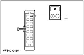
4Measure the voltage between pin 2 of the heater blower motor connector C537 (right-hand drive vehicles: pin 1), circuit 15S-FA18 (green/orange), wiring harness side, and ground. |
|
• Is battery voltage registered? |
|
|
→ Yes |
|
|
Go to J4 |
|
|
→ No |
|
|
LOCATE and REPAIR the open in the electrical circuit between the heater blower motor and fuse F64 using the wiring diagrams. CHECK the correct operation of the system. |
|
|
J4: CHECKING THE ELECTRICAL GROUND CIRCUIT OF THE HEATER ELECTRIC FAN |
|
|
1Enter the OFF position. |
|
|
2Measure the resistance between pin 1 of the heater blower motor connector C537 (right-hand drive vehicles: pin 2), circuit 31-FA45 (black), wiring harness side and ground. |
|
• Is the measured resistance less than 2 ohms? |
|
|
→ Yes |
|
|
Go to J5 |
|
|
→ No |
|
|
LOCATE and REPAIR the open in the electrical circuit between the heater blower motor and ground point G14 using the wiring diagrams. CHECK the system for proper operation. |
|
|
J5: CHECKING THE ELECTRICAL CIRCUITS BETWEEN THE HEATER FAN MODULE AND THE EATC MODULE |
|
|
1Disconnect C539 of EATC module. |
|
|
2Measure the resistance between pin 3 of the heater blower motor connector C537 (right-hand drive vehicles: pin 5), circuit 9-FA45 (BRN/BU), wiring harness side and pin 26 of the EATC module connector C539, circuit 9-FA45 (BRN/BU), wiring harness side. |
|
3Measure the resistance between pin 6 of the heater blower motor connector C537 (right-hand drive vehicles: pin 4), circuit 49S-FA45 (white/blue), wiring harness side and pin 25 of the EATC module connector C539, circuit 49S-FA45 (white/blue), wiring harness side. |
|
• Is the measured resistance less than 2 ohms in both cases? |
|
|
→ Yes |
|
|
Go to J6 |
|
|
→ No |
|
|
LOCATE and REPAIR the open in the 9-FA45 (Brown/Blue) or 49S-FA45 (White/Blue) circuit between the heater blower motor and the EATC module using the wiring diagrams. CHECK for proper system operation. |
|
|
J6: CHECKING THE ELECTRICAL CIRCUITS BETWEEN THE EATC MODULE AND THE HEATER FAN MOTOR FOR A SHORT CIRCUIT TO BATTERY + |
|
|
1Enter the ON position. |
|
|
2Measure the voltage between pin 26 of the EATC module connector C539, circuit 9-FA45 (brown/blue), wiring harness side, and ground. |
|
3Measure the voltage between pin 25 of the EATC module connector C539, circuit 49S-FA45 (white/blue), wiring harness side, and ground. |
|
|
• Is voltage recorded when each of these measurements is made? |
|
|
→ Yes |
|
|
Go to J7 |
|
|
→ No |
|
|
LOCATE and REPAIR the short to battery in the 9-FA45 (BRN/BLUE) or 49S-FA45 (WH/BLUE) circuit between the heater blower motor and the EATC module using the wiring diagrams. CHECK for proper system operation. |
|
|
J7: CHECK THE ELECTRICAL CIRCUITS BETWEEN THE EATC MODULE AND THE HEATER FAN MOTOR FOR A SHORT CIRCUIT "MASS" |
|
|
1Enter the OFF position. |
|
|
2Measure the resistance between pin 26 of the EATC module connector C539, circuit 9-FA45 (brown/blue), wiring harness side, and ground. |
|
3Measure the resistance between pin 25 C539 of the EATC module connector, circuit 49S-FA45 (white/blue), wiring harness side, and ground. |
|
|
• Is the measured resistance greater than 10 kOhm in both cases? |
|
|
→ Yes |
|
|
Go to J8 |
|
|
→ No |
|
|
LOCATE and REPAIR the short to ground in the 9-FA45 (BRN/BLUE) or 49S-FA45 (WH/BLUE) circuit between the heater blower motor and the EATC module using the Wiring Diagrams. CHECK for proper system operation. |
|
|
J8: CHECKING THE HEATER ELECTRIC FAN |
|
|
1Connect C537 heater fan. |
|
|
2Enter the ON position. |
|
|
• Does the heater fan operate at approximately half power? |
|
|
→ Yes |
|
|
CHECK and if necessary REPLACE the EATC module. CHECK that the system is operating correctly. |
|
|
→ No |
|
|
REPLACE the heater blower. CHECK the system for proper operation. |
|
PINPOINT TEST K: AIR RECIRCULATION FLAP MALFUNCTIONING (EATC VEHICLES ONLY)
|
STATES |
DETAILS/RESULTS/ACTIONS |
|
NOTE:The air recirculation flap is driven by a DC motor. After pressing the air recirculation button, this DC motor is activated by the EATC control module for a maximum of 7 seconds. The opening and closing of the air recirculation flap is performed by changing the polarity of the supplied voltage. |
|
|
NOTE:If the "anti-fog/anti-icing" button is pressed, the air recirculation mode cannot be switched on. |
|
|
K1: CHECKING THE VOLTAGE IN THE AIR RECIRCULATION FLAP POSITIONING MOTOR CIRCUIT |
|
|
1Enter the OFF position. |
|
|
2Disconnect C538 air recirculation flap positioning motor. |
|
|
3Enter the ON position. |
|
|
4Measure the voltage between pins 2 and 4 of the air recirculation flap positioning motor connector C538, on the wiring harness side. |
|
|
5During the measurement process, press the air recirculation button several times. |
|
|
• Is the voltage registered at about 11 V with alternating polarity? |
|
|
→ Yes |
|
|
CHECK the air recirculation flap for freedom of movement and proper operation. If the air recirculation flap is mechanically OK, REPLACE the air recirculation flap positioning motor. CHECK the system for proper operation. |
|
|
→ No |
|
|
Go to K2 |
|
|
K2: CHECKING THE ELECTRICAL CIRCUIT BETWEEN THE AIR RECIRCULATION FLAP POSITIONING MOTOR AND THE EATC MODULE FOR OPENING |
|
|
1Enter the OFF position. |
|
|
2Disconnect C539 of EATC module. |
|
|
3Measure the resistance between pin 2 of the air recirculation flap servo motor C538, circuit 33-FA76 (YE/BU) (RHD vehicles: circuit 32-FA76 (WH/BU)), wiring harness side and pin 17 of the EATC module 17 connector C539, circuit 33-FA76 (YE/BU), wiring harness side. |
|
|
4Measure the resistance between pin 4 of the air recirculation flap servo motor C538, circuit 32-FA76 (WH/BU) (right-hand drive vehicles: circuit 33-FA76 (YE/BU)), wiring harness side and pin 1 of the EATC module 1 connector C539, circuit 32-FA76 (WH/BU), wiring harness side. |
|
|
• Is the measured resistance less than 2 ohms in both cases? |
|
|
→ Yes |
|
|
Go to K3 |
|
|
→ No |
|
|
LOCATE and REPAIR the open in circuit 32-FA76 (white/blue) or 33-FA76 (yellow/blue) between the air recirculation flap positioning motor and the EATC module using the Wiring Diagrams. CHECK for proper system operation. |
|
|
K3: CHECK THE ELECTRICAL CIRCUIT BETWEEN THE AIR RECIRCULATION FLAP POSITIONING MOTOR AND THE EATC MODULE FOR A SHORT TO BATTERY + |
|
|
1Enter the ON position. |
|
|
2Measure the voltage between pin 17 of the EATC module connector C539, circuit 33-FA76 (yellow/blue), wiring harness side, and ground. |
|
3Measure the voltage between pin 1 of EATC module connector C539, circuit 32-FA76 (white/blue), wiring harness side, and ground. |
|
|
• Is voltage recorded when each of these measurements is made? |
|
|
→ Yes |
|
|
LOCATE and REPAIR the short to battery voltage in circuit 32-FA76 (WH/BLK) or 33-FA76 (YEL/BLK) between the air recirculation flap positioning motor and the EATC module using the Wiring Diagrams. CHECK for proper system operation. |
|
|
→ No |
|
|
Go to K4 |
|
|
K4: CHECK THE ELECTRICAL CIRCUIT BETWEEN THE AIR RECIRCULATION FLAP POSITIONING MOTOR AND THE EATC MODULE FOR A SHORT CIRCUIT "MASS" |
|
|
1Enter the OFF position. |
|
|
2Measure the resistance between pin 17 of the EATC module connector C539, circuit 33-FA76 (yellow/blue), wiring harness side, and ground. |
|
3Measure the resistance between pin 1 of the EATC module connector C539, circuit 32-FA76 (white/blue), wiring harness side, and ground. |
|
|
• Is the measured resistance greater than 10 kOhm in both cases? |
|
|
→ Yes |
|
|
CHECK and if necessary REPLACE the EATC module. CHECK that the system is operating correctly. |
|
|
→ No |
|
|
LOCATE and REPAIR the short to ground in circuit 32-FA76 (WH/BL) or 33-FA76 (YE/BL) between the air recirculation flap positioning motor and the EATC module using the Wiring Diagrams. CHECK for proper system operation. |
|
PINPOINT TEST L: ANTI-ICE FLAP MALFUNCTIONING (EATC VEHICLES ONLY)
|
STATES |
DETAILS/RESULTS/ACTIONS |
|
L1: CHECKING ELECTRICAL CIRCUITS BETWEEN ANTI-FREEZE FLAP POSITIONING MOTOR AND EATC MODULE FOR OPEN CIRCUIT |
|
|
1Enter the OFF position. |
|
|
2Disconnect C539 of EATC module. |
|
|
3Disconnect C532 defrost flap positioning motor. |
|
|
4Measure the resistance between pin 2 of defrost flap servo motor C532, circuit 15S-FB14 (GN/BU), wiring harness side and pin 10 of EATC module connector C539, circuit 15S-FB1 (GN/YE), wiring harness side. |
|
5Measure the resistance between pin 1 of defrost flap servo motor C532, circuit 31S-FB15 (BK/OG), wiring harness side and pin 11 of EATC module connector C539, circuit 31S-FB15 (BK/BU), wiring harness side. |
|
6Measure the resistance between pin 3 of defrost flap servo motor C532, circuit 31S-FB16 (BK/GN), wiring harness side and pin 12 of EATC module connector C539, circuit 31S-FB16 (BK/GN), wiring harness side. |
|
7Measure the resistance between pin 4 of defrost flap servo motor C532, circuit 31S-FB17 (BK/RD), wiring harness side and pin 27 of EATC module connector C539, circuit 31S-FB17 (BK/RD), wiring harness side. |
|
8Measure the resistance between pin 6 of defrost flap servo motor C532, circuit 31S-FB18 (BK/WH), wiring harness side and pin 28 of EATC module connector C539, circuit 31S-FB18 (BK/WH), wiring harness side. |
|
• In all cases, is the measured resistance less than 2 ohms? |
|
|
→ Yes |
|
|
Go to L2 |
|
|
→ No |
|
|
LOCATE and REPAIR the open in the circuit in question between the defrost flap positioning motor and the EATC module using the wiring diagrams. CHECK the correct operation of the system. |
|
|
L2: CHECK THE ELECTRICAL CIRCUITS BETWEEN THE ANTI-FREEZE FLAP POSITIONING MOTOR AND THE EATC MODULE FOR A SHORT TO BATTERY + |
|
|
1Enter the ON position. |
|

|
2Measure the voltage between pin 2 of the defrost flap positioning motor C532, circuit 15S-FB14 (GN/BU), wiring harness side and ground. |

|
3Measure the voltage between pin 1 of the defrost flap positioning motor C532, circuit 31S-FB15 (BK/OG), wiring harness side and ground. |
|
4Measure the voltage between pin 3 of the defrost flap positioning motor connector C532, circuit 31S-FB16 (black/green), wiring harness side and ground. |

|
5Measure the voltage between pin 4 of the defrost flap positioning motor connector C532, circuit 31S-FB17 (BK/RED), wiring harness side and ground. |
|
6Measure the voltage between pin 6 of the defrost flap positioning motor connector C532, circuit 31S-FB18 (BK/WH), wiring harness side and ground. |
|
• Is voltage recorded when each of these measurements is made? |
|
|
→ Yes |
|
|
LOCATE and REPAIR the short to battery voltage in the circuit in question between the defrost flap positioning motor and the EATC module using the wiring diagrams. CHECK for proper system operation. |
|
|
→ No |
|
|
Go to L3 |
|
|
L3: CHECK THE ELECTRICAL CIRCUITS BETWEEN THE ANTI-ICE FLAP POSITIONING MOTOR AND THE EATC MODULE FOR A SHORT CIRCUIT "MASS" |
|
|
1Enter the OFF position. |
|

|
2Measure the resistance between pin 2 of the defrost flap positioning motor C532, circuit 15S-FB14 (GN/BU), wiring harness side and ground. |

|
3Measure the resistance between pin 1 of connector C532 of the defrost flap positioning motor, circuit 31S-FB15 (Black/Orange), wiring harness side and ground. |

|
4Measure the resistance between pin 3 of the defrost flap positioning motor C532, circuit 31S-FB16 (black/green), wiring harness side and ground. |

|
5Measure the resistance between pin 4 of connector C532 of the defrost flap positioning motor, circuit 31S-FB17 (BK/RED), wiring harness side and ground. |

|
6Measure the resistance between pin 6 of the defrost flap positioning motor connector C532, circuit 31S-FB18 (BK/WH), wiring harness side and ground. |
|
• Is the measured resistance greater than 10 kOhm in all cases? |
|
|
→ Yes |
|
|
CHECK the defrost flap for freedom of movement and proper operation. If the defrost flap is mechanically OK, REPLACE the defrost flap positioning motor. CHECK the system for proper operation. |
|
|
→ No |
|
|
LOCATE and REPAIR the short to ground in the circuit in question between the defrost flap positioning motor and the EATC module using the wiring diagrams. CHECK the system for proper operation. |
|
PINPOINT TEST M: AIR DISTRIBUTION FLAP MALFUNCTIONING (EATC VEHICLES ONLY)
|
STATES |
DETAILS/RESULTS/ACTIONS |
|
M1: CHECKING THE INSTRUMENT PANEL/FOOT CUP FLAP POSITIONING MOTOR AND EATC MODULE FOR OPEN CIRCUIT |
|
|
1Enter the OFF position. |
|
|
2Disconnect C539 of EATC module. |
|
|
3Disconnect C533 Instrument Panel/Footwell Flap Positioning Motor. |
|
|
4Measure the resistance between pin 2 of instrument panel/footwell flap servo motor C533, circuit 15S-FB19 (GN/YE), wiring harness side and pin 10 of EATC module connector C539, circuit 15S-FB1 (GN/YE), wiring harness side. |
|
5Measure the resistance between pin 1 of instrument panel/footwell flap servo motor C533, circuit 31S-FB20 (BK/BU), wiring harness side and pin 13 of EATC module connector C539, circuit 31S-FB20 (BK/BU), wiring harness side. |
|
6Measure the resistance between pin 3 of instrument panel/footwell flap servo motor C533, circuit 31S-FB21 (BK/OG), wiring harness side and pin 14 of EATC module connector C539, circuit 31S-FB21 (BK/OG), wiring harness side. |
|
7Measure the resistance between pin 4 of instrument panel/footwell flap servo motor C533, circuit 31S-FB22 (BK/GN), wiring harness side and pin 29 of EATC module connector C539, circuit 31S-FB22 (BK/GN), wiring harness side. |
|
8Measure the resistance between pin 6 of instrument panel/footwell flap servo motor connector C533, circuit 31S-FB23 (BK/RD), wiring harness side and pin 30 of EATC module connector C539, circuit 31S-FB23 (BK/RD), wiring harness side. |
|
• In all cases, is the measured resistance less than 2 ohms? |
|
|
→ Yes |
|
|
Go to M2 |
|
|
→ No |
|
|
LOCATE and REPAIR the open in the circuit in question between the instrument panel/footwell flap positioner motor and the EATC module using the wiring diagrams. CHECK the system for proper operation. |
|
|
M2: CHECK THE ELECTRICAL CIRCUITS BETWEEN THE INSTRUMENT PANEL/FOOT CUP FLAP POSITIONING MOTOR AND THE EATC MODULE FOR SHORT TO BATTERY + |
|
|
1Enter the ON position. |
|

|
2Measure the voltage between pin 2 of instrument panel/footwell flap servo motor connector C533, circuit 15S-FB19 (GN/YE), wiring harness side and ground. |
|
3Measure the voltage between pin 1 of instrument panel/footwell flap servo motor connector C533, circuit 31S-FB20 (BLK/BU), wiring harness side and ground. |

|
4Measure the voltage between pin 3 of instrument panel/footwell flap servo motor connector C533, circuit 31S-FB21 (BK/OG), wiring harness side and ground. |

|
5Measure the voltage between pin 4 of instrument panel/footwell flap servo motor connector C533, circuit 31S-FB22 (GN/BK), wiring harness side and ground. |

|
6Measure the voltage between pin 6 of instrument panel/footwell flap servo motor connector C533, circuit 31S-FB23 (BK/RD), wiring harness side and ground. |
|
• Is voltage recorded when each of these measurements is made? |
|
|
→ Yes |
|
|
LOCATE and REPAIR the short to battery voltage in the circuit in question between the instrument panel/footwell flap positioner motor and the EATC module using the Wiring Diagrams. CHECK for proper system operation. |
|
|
→ No |
|
|
Go to M3 |
|
|
M3: CHECK THE ELECTRICAL CIRCUITS BETWEEN THE INSTRUMENT PANEL/FOOT CUP FLAP POSITIONING MOTOR AND THE EATC MODULE FOR SHORT CIRCUIT "MASS" |
|
|
1Enter the OFF position. |
|
|
2Measure the resistance between pin 2 of instrument panel/footwell flap servo motor connector C533, circuit 15S-FB19 (GN/YE), wiring harness side and ground. |
|
3Measure the resistance between pin 1 of instrument panel/footwell flap servo motor connector C533, circuit 31S-FB20 (BLK/BU), wiring harness side and ground. |
|
4Measure the resistance between pin 3 of instrument panel/footwell flap servo motor connector C533, circuit 31S-FB21 (BK/OG), wiring harness side and ground. |
|
5Measure the resistance between pin 4 of instrument panel/footwell flap servo motor connector C533, circuit 31S-FB22 (GN/BK), wiring harness side and ground. |

|
6Measure the resistance between pin 6 of instrument panel/footwell flap servo motor connector C533, circuit 31S-FB23 (BK/RED), wiring harness side and ground. |
|
• Is the measured resistance greater than 10 kOhm in all cases? |
|
|
→ Yes |
|
|
CHECK the distribution flap for freedom of movement and proper operation. If the air distribution flap is mechanically OK, REPLACE the instrument panel/footwell flap positioning motor. CHECK the system for proper operation. |
|
|
→ No |
|
|
LOCATE and REPAIR the short to ground in the circuit in question between the instrument panel/footwell flap positioner motor and the EATC module using the Wiring Diagrams. CHECK for proper system operation. |
|
PINPOINT TEST N: AIR TEMPERATURE FLAP MALFUNCTIONING (EATC VEHICLES ONLY)
|
STATES |
DETAILS/RESULTS/ACTIONS |
|
N1: CHECKING THE ELECTRICAL CIRCUITS BETWEEN THE AIR TEMPERATURE FLAP POSITIONING MOTOR AND THE EATC MODULE FOR OPEN CIRCUIT |
|
|
1Enter the OFF position. |
|
|
2Disconnect C539 of EATC module. |
|
|
3Disconnect C534 air temperature flap positioning motor. |
|
|
4Measure the resistance between pin 2 of the air temperature flap servo motor C534, circuit 15S-FB9 (GN/RD), wiring harness side and pin 10 of the EATC module connector C539, circuit 15S-FB1 (GN/YE), wiring harness side. |
|
5Measure the resistance between pin 1 of air temperature flap servo motor connector C534, circuit 31S-FB10 (GN/BLK), wiring harness side and pin 15 of EATC module connector C539, circuit 31S-FB10 (GN/BLK), wiring harness side. |
|
6Measure the resistance between pin 3 of the air temperature flap servo motor C534, circuit 31S-FB11 (BK/RD), wiring harness side and pin 16 of the EATC module connector C539, circuit 31S-FB11 (BK/RD), wiring harness side. |
|
7Measure the resistance between pin 4 of air temperature flap servo motor connector C534, circuit 31S-FB12 (BK/WH), wiring harness side and pin 31 of EATC module connector C539, circuit 31S-FB12 (BK/WH), wiring harness side. |
|
8Measure the resistance between pin 6 of the air temperature flap servo motor connector C534, circuit 31S-FB13 (BK/YE), wiring harness side and pin 32 of the EATC module connector C539, circuit 31S-FB13 (BK/YE), wiring harness side. |
|
• In all cases, is the measured resistance less than 2 ohms? |
|
|
→ Yes |
|
|
Go to N₂ |
|
|
→ No |
|
|
LOCATE and REPAIR the open in the circuit in question between the air temperature flap positioning motor and the EATC module using the wiring diagrams. CHECK the correct operation of the system. |
|
|
N₂: CHECKING THE ELECTRICAL CIRCUITS BETWEEN THE AIR TEMPERATURE FLAP POSITIONING MOTOR AND THE EATC MODULE FOR A SHORT CIRCUIT TO BATTERY + |
|
|
1Enter the ON position. |
|
|
2Measure the voltage between pin 2 of the air temperature flap servo motor connector C534, circuit 15S-FB9 (green/red), wiring harness side and ground. |

|
3Measure the voltage between pin 1 of the air temperature flap servo motor connector C534, circuit 31S-FB10 (black/green), wiring harness side and ground. |
|
4Measure the voltage between pin 3 of the air temperature flap servo motor connector C534, circuit 31S-FB11 (BK/RED), wiring harness side and ground. |
|
5Measure the voltage between pin 4 of the air temperature flap servo motor connector C534, circuit 31S-FB12 (BK/WH), wiring harness side and ground. |

|
6Measure the voltage between pin 6 of the air temperature flap servo motor connector C534, circuit 31S-FB13 (BK/YE), wiring harness side and ground. |
|
• Is voltage recorded when each of these measurements is made? |
|
|
→ Yes |
|
|
LOCATE and REPAIR the short to battery in the circuit in question between the air temperature flap positioning motor and the EATC module using the wiring diagrams. CHECK the system for proper operation. |
|
|
→ No |
|
|
Go to N3 |
|
|
N3: CHECK THE ELECTRICAL CIRCUITS BETWEEN THE AIR TEMPERATURE FLAP POSITIONING MOTOR AND THE EATC MODULE FOR A SHORT CIRCUIT "MASS" |
|
|
1Enter the OFF position. |
|

|
2Measure the resistance between pin 2 of the air temperature flap servo motor connector C534, circuit 15S-FB9 (green/red), wiring harness side and ground. |

|
3Measure the resistance between pin 1 of the air temperature flap servo motor connector C534, circuit 31S-FB10 (black/green), wiring harness side and ground. |

|
4Measure the resistance between pin 3 of the air temperature flap servo motor connector C534, circuit 31S-FB11 (BK/RED), wiring harness side and ground. |

|
5Measure the resistance between pin 4 of the air temperature flap servo motor connector C534, circuit 31S-FB12 (BK/WH), wiring harness side and ground. |
|
6Measure the resistance between pin 6 of the air temperature flap servo motor connector C534, circuit 31S-FB13 (BK/YE), wiring harness side and ground. |
|
• Is the measured resistance greater than 10 kOhm in all cases? |
|
|
→ Yes |
|
|
CHECK the air temperature flap for freedom of movement and proper operation. If the air temperature flap is mechanically OK, REPLACE the air temperature flap positioning motor. CHECK the system for proper operation. |
|
|
→ No |
|
|
LOCATE and REPAIR the short to ground in the circuit in question between the air temperature flap positioning motor and the EATC module using the wiring diagrams. CHECK for proper system operation. |
|
PINPOINT TEST O: FOOT CUP OUTLET AIR TEMPERATURE SENSOR CIRCUIT MALFUNCTION (EATC VEHICLES ONLY)
|
STATES |
DETAILS/RESULTS/ACTIONS |
|
O1: CHECK FOR OPEN CIRCUIT BETWEEN FOOT CUP OUTLET AIR TEMPERATURE SENSOR AND EATC MODULE |
|
|
1Enter the OFF position. |
|
|
2Disconnect C539 of EATC module. |
|
|
3Disconnect C536 footwell outlet air temperature sensor. |
|
|
4Measure the resistance between pin 1 of the footwell outlet air temperature sensor C536, circuit 8-FA51 (WH/BLK), wiring harness side and pin 8 of the EATC module connector C539, circuit 8-FA51 (WH/BLK), wiring harness side. |

|
5Measure the resistance between pin 2 of the footwell outlet air temperature sensor C536, circuit 9-FA51 (BRN/YE), harness side and pin 7 of the EATC module connector C539, circuit 9-FA3 (BRN/RED), harness side. |
|
• Is the measured resistance less than 2 ohms in both cases? |
|
|
→ Yes |
|
|
Go to O2 |
|
|
→ No |
|
|
LOCATE and REPAIR the open in the circuit in question between the footwell outlet air temperature sensor and the EATC module using the wiring diagrams. CHECK the system for proper operation. |
|
|
O2: CHECK THE ELECTRICAL CIRCUIT BETWEEN THE FOOT CUP OUTLET AIR TEMPERATURE SENSOR AND THE EATC MODULE FOR A SHORT TO BATTERY + |
|
|
1Enter the ON position. |
|

|
2Measure the voltage between pin 1 of the footwell outlet air temperature sensor connector C536, circuit 8-FA51 (WH/BLK), wiring harness side and ground. |
|
3Measure the voltage between pin 2 of the footwell outlet air temperature sensor connector C536, circuit 9-FA51 (BN/YE), wiring harness side and ground. |
|
|
• Is voltage recorded when each of these measurements is made? |
|
|
→ Yes |
|
|
LOCATE and REPAIR the short to battery in the circuit in question between the footwell outlet air temperature sensor and the EATC module using the wiring diagrams. CHECK for proper system operation. |
|
|
→ No |
|
|
Go to O3 |
|
|
O3: CHECK THE ELECTRICAL CIRCUIT BETWEEN THE FOOT CUP OUTLET AIR TEMPERATURE SENSOR AND THE EATC MODULE FOR A SHORT CIRCUIT "MASS" |
|
|
1Enter the OFF position. |
|
|
2Measure the resistance between pin 1 of the footwell outlet air temperature sensor connector C536, circuit 8-FA51 (WH/BLK), wiring harness side and ground. |
|
3Measure the resistance between pin 2 of the footwell outlet air temperature sensor connector C536, circuit 9-FA51 (BN/YE), wiring harness side and ground. |
|
|
• Is the measured resistance greater than 10 kOhm in both cases? |
|
|
→ Yes |
|
|
REPLACE the footwell outlet air temperature sensor. CHECK the system for proper operation. |
|
|
→ No |
|
|
LOCATE and REPAIR the short to ground in the circuit in question between the footwell outlet air temperature sensor and the EATC module using the Wiring Diagrams. CHECK for proper system operation. |
|
PINPOINT TEST P: MALFUNCTION IN THE INSTRUMENT PANEL OUTLET AIR TEMPERATURE SENSOR CIRCUIT (EATC VEHICLES ONLY)
|
STATES |
DETAILS/RESULTS/ACTIONS |
|
P1: CHECK THE ELECTRICAL CIRCUIT BETWEEN THE INSTRUMENT PANEL OUTLET AIR TEMPERATURE SENSOR AND THE EATC MODULE FOR OPEN CIRCUIT |
|
|
1Enter the OFF position. |
|
|
2Disconnect C539 of EATC module. |
|
|
3Disconnect C535 instrument panel outlet air temperature sensor. |
|
|
4Measure the resistance between pin 1 of the instrument cluster outlet air temperature sensor connector C535, circuit 8-FA47 (WH/GN), wiring harness side and pin 9 of the EATC module connector C539, circuit 8-FA47 (WH/GN), wiring harness side. |
|
5Measure the resistance between pin 2 of the instrument cluster outlet air temperature sensor connector C535, circuit 9-FA47 (BRN/GRN), wiring harness side and pin 7 of the EATC module connector C539, circuit 9-FA3 (BRN/RED), wiring harness side. |
|
• Is the measured resistance less than 2 ohms in both cases? |
|
|
→ Yes |
|
|
Go to P2 |
|
|
→ No |
|
|
LOCATE and REPAIR the open in the circuit in question between the instrument cluster outlet air temperature sensor and the EATC module using the wiring diagrams. CHECK the system for proper operation. |
|
|
P2: CHECK THE ELECTRICAL CIRCUIT BETWEEN THE INSTRUMENT PANEL OUTLET AIR TEMPERATURE SENSOR AND THE EATC MODULE FOR A SHORT TO BATTERY + |
|
|
1Enter the ON position. |
|
|
2Measure the voltage between pin 1 of the instrument cluster outlet air temperature sensor connector C535, circuit 8-FA47 (green/white), wiring harness side, and ground. |
|
3Measure the voltage between pin 2 of the instrument cluster outlet air temperature sensor connector C535, circuit 9-FA47 (brown/green), wiring harness side, and ground. |
|
|
• Is voltage recorded when each of these measurements is made? |
|
|
→ Yes |
|
|
LOCATE and REPAIR the short to battery in the circuit in question between the instrument cluster outlet air temperature sensor and the EATC module using the wiring diagrams. CHECK the system for proper operation. |
|
|
→ No |
|
|
Go to P3 |
|
|
P3: CHECK THE ELECTRICAL CIRCUIT BETWEEN THE INSTRUMENT PANEL OUTLET AIR TEMPERATURE SENSOR AND THE EATC MODULE FOR A SHORT CIRCUIT "MASS" |
|
|
1Enter the OFF position. |
|

|
2Measure the resistance between pin 1 of the instrument cluster outlet air temperature sensor connector C535, circuit 8-FA47 (green/white), wiring harness side, and ground. |
|
3Measure the resistance between pin 2 of the instrument cluster outlet air temperature sensor connector C535, circuit 9-FA47 (brown/green), wiring harness side, and ground. |
|
|
• Is the measured resistance greater than 10 kOhm in both cases? |
|
|
→ Yes |
|
|
REPLACE the instrument cluster outlet air temperature sensor. CHECK the system for proper operation. |
|
|
→ No |
|
|
LOCATE and REPAIR the short to ground in the circuit in question between the instrument cluster outlet air temperature sensor and the EATC module using the wiring diagrams. CHECK the system for proper operation. |
|
PINPOINT TEST Q: MALFUNCTION IN SOLAR INTENSITY SENSOR CIRCUIT (EATC VEHICLES ONLY)
|
STATES |
DETAILS/RESULTS/ACTIONS |
|
Q1: CHECKING THE ELECTRICAL CIRCUIT BETWEEN THE SOLAR INTENSITY SENSOR AND THE EATC MODULE FOR OPEN CIRCUIT |
|
|
1Enter the OFF position. |
|
|
2Disconnect C539 of EATC module. |
|
|
3Disconnect C467 trip computer module. |
|
|
4Disconnect C531 solar radiation sensor. |
|
|
5Measure the resistance between pin 1 of connector C531 of the sun intensity sensor, circuit 8-FA53 (WH/BU), wiring harness side and pin 24 of connector C539 of the EATC module, circuit 8-FA53 (WH/BU), wiring harness side. |
|
6Measure the resistance between pin 2 of the sun intensity sensor connector C531, circuit 9-FA53 (BRN/BLK), wiring harness side and pin 19 of the EATC module connector C539, circuit 9-FA1 (BRN/RED), wiring harness side. |
|
• Is the measured resistance less than 2 ohms in both cases? |
|
|
→ Yes |
|
|
Go to Q2 |
|
|
→ No |
|
|
LOCATE and REPAIR the open in the circuit in question between the solar radiation sensor and the EATC module using the wiring diagrams. CHECK that the system is operating correctly. |
|
|
Q2: CHECK THE ELECTRICAL CIRCUIT BETWEEN THE SOLAR INTENSITY SENSOR AND THE EATC MODULE FOR A SHORT CIRCUIT TO BATTERY + |
|
|
1Enter the ON position. |
|

|
2Measure the voltage between pin 1 of the solar radiation sensor connector C531, circuit 8-FA53 (blue/white), wiring harness side, and ground. |
|
3Measure the voltage between pin 2 of the solar radiation sensor connector C531, circuit 9-FA53 (BRN/BLUE), wiring harness side, and ground. |
|
|
• Is voltage recorded when each of these measurements is made? |
|
|
→ Yes |
|
|
LOCATE and REPAIR the short to battery + in the circuit in question between the solar radiation sensor and the EATC module using the wiring diagrams. CHECK the system for proper operation. |
|
|
→ No |
|
|
Go to Q3 |
|
|
Q3: CHECK THE ELECTRICAL CIRCUIT BETWEEN THE SOLAR INTENSITY SENSOR AND THE EATC MODULE FOR A SHORT CIRCUIT "MASS" |
|
|
1Enter the OFF position. |
|
|
2Measure the resistance between pin 1 of connector C531 of the sun intensity sensor, circuit 8-FA53 (white/blue), wiring harness side, and ground. |
|
3Measure the resistance between pin 2 of the solar radiation sensor connector C531, circuit 9-FA53 (brown/blue), wiring harness side, and ground. |
|
|
• Is the measured resistance greater than 10 kOhm in both cases? |
|
|
→ Yes |
|
|
REPLACE the solar radiation sensor. CHECK the system for proper operation. |
|
|
→ No |
|
|
LOCATE and REPAIR the short to ground in the circuit in question between the solar radiation sensor and the EATC module using the wiring diagrams. CHECK the system for proper operation. |
|
PINPOINT TEST R: ELECTRICAL CIRCUIT FAULT BETWEEN EATC MODULE AND TRIP COMPUTER MODULE (VEHICLES WITHOUT DURATEC-ST ENGINE ONLY)
|
STATES |
DETAILS/RESULTS/ACTIONS |
|
R1: CHECK THE ELECTRICAL CIRCUIT BETWEEN THE TRIP COMPUTER MODULE AND THE EATC MODULE FOR OPEN CIRCUIT |
|
|
1Enter the OFF position. |
|
|
2Disconnect C539 of EATC module. |
|
|
3Disconnect C467 trip computer module. |
|
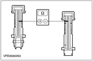
|
4Measure the resistance between trip computer module connector C467 pin 8, circuit 9-FA48 (BRN/GN), wiring harness side and EATC module connector C539 pin 19, circuit 9-FA1 (BRN/RED), wiring harness side. |
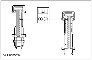
|
5Measure the resistance between pin 9 of the trip computer module connector C467, circuit 8-FA48 (WH/GN), wiring harness side and pin 18 of the EATC module connector C539, circuit 8-FA48 (WH/GN), wiring harness side. |
|
• Is the measured resistance less than 2 ohms in both cases? |
|
|
→ Yes |
|
|
Go to R2 |
|
|
→ No |
|
|
LOCATE and REPAIR the open in the circuit in question between the trip computer module and the EATC module using the wiring diagrams. CHECK the system for proper operation. |
|
|
R2: CHECK THE ELECTRICAL CIRCUIT BETWEEN THE TRIP COMPUTER MODULE AND THE EATC MODULE FOR A SHORT TO BATTERY + |
|
|
1Enter the ON position. |
|
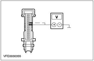
|
2Measure the voltage between pin 8 of the trip computer module connector C467, circuit 9-FA48 (brown/green), wiring harness side, and ground. |
|
3Measure the voltage between pin 9 of the trip computer module connector C467, circuit 8-FA48 (green/white), wiring harness side, and ground. |
|
|
• Is voltage recorded when each of these measurements is made? |
|
|
→ Yes |
|
|
LOCATE and REPAIR the short to battery in the circuit in question between the trip computer module and the EATC module using the wiring diagrams. CHECK the system for proper operation. |
|
|
→ No |
|
|
Go to R3 |
|
|
R3: CHECK THE ELECTRICAL CIRCUIT BETWEEN THE TRIP COMPUTER MODULE AND THE EATC MODULE FOR A SHORT CIRCUIT "MASS" |
|
|
1Enter the OFF position. |
|
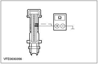
|
2Measure the resistance between pin 8 of the trip computer module connector C467, circuit 9-FA48 (brown/green), wiring harness side, and ground. |
|
3Measure the resistance between pin 9 of the trip computer module connector C467, circuit 8-FA48 (green/white), wiring harness side, and ground. |
|
|
• Is the measured resistance greater than 10 kOhm in both cases? |
|
|
→ Yes |
|
|
CHECK and if necessary REPLACE the trip computer module. CHECK that the system is operating correctly. |
|
|
→ No |
|
|
LOCATE and REPAIR the short to ground in the circuit in question between the trip computer module and the EATC module using the wiring diagrams. CHECK the system for proper operation. |
|
(The original post is on the web portal FordBook)