|
STATES |
DETAILS/RESULTS/ACTIONS |
|
A1: CHECKING THE OPERATION OF THE A/C COMPRESSOR CLUTCH |
|
|
1Enter the START position. |
|
|
2Turn on the air conditioning system. |
|
|
3Turn on the heater fan. |
|
|
4Check the operation of the air conditioning compressor clutch. |
|
|
• Is the air conditioning compressor clutch working? |
|
|
→ Yes |
|
|
CHECK the refrigerant circuit and the amount of refrigerant and ADJUST if necessary. CHECK the correct operation of the system. |
|
|
→ No |
|
|
Go to A2 |
|
|
A2: READING FDS/WDS FAULT CODES |
|
|
1Enter the OFF position. |
|
|
2Run the Engine Management System Diagnostic Program to retrieve trouble codes using FDS/WDS. |
|
|
• Is there a fault code related to the air conditioning system? |
|
|
→ Yes |
|
|
PERFORM the necessary troubleshooting steps as directed by the FDS/WDS. CHECK that the system is operating correctly. |
|
|
→ No |
|
|
Go to A3 |
|
|
A3: CHECKING FUSE F58 |
|
|
1CHECK Fuse F58 (CJB). |
|
|
• Is the fuse good? |
|
|
→ Yes |
|
|
Go to A4 |
|
|
→ No |
|
|
REPLACE fuse F58 (7.5A). If the fuse blows again after turning on the A/C system, CHECK the A/C compressor clutch diode and REPLACE it if necessary. If the diode is OK, LOCATE and REPAIR the short to ground using the wiring diagrams. CHECK the system for proper operation. |
|
|
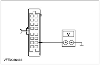
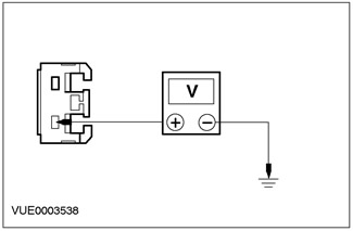
A4: CHECKING THE VOLTAGE AT FUSE F58 |
|
|
1Connect Fuse F58 (CJB). |
|
|
2Enter the ON position. |
|
|
3Check the voltage in the electrical circuit between fuse F58 (7.5 A) and ground. |
|
|
• Is battery voltage registered? |
|
|
→ Yes |
|
|
Go to A5 |
|
|
→ No |
|
|
RESTORE power to fuse F58 using the wiring diagrams. CHECK that the system is operating correctly. |
|
|
A5: CHECKING FUSE F36 |
|
|
1Enter the OFF position. |
|
|
2CHECK Fuse F36 (CJB). |
|
|
• Is the fuse good? |
|
|
→ Yes |
|
|
Go to A6 |
|
|
→ No |
|
|
REPLACE fuse F36 (7.5A). If the fuse blows again, LOCATE and REPAIR the short to ground using the wiring diagrams. CHECK the system for proper operation. |
|
|
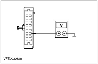
A6: CHECKING THE VOLTAGE AT FUSE F36 |
|
|
1Connect Fuse F36 (CJB). |
|
|
2Check the voltage in the electrical circuit between fuse F36 (7.5 A) and ground. |
|
|
• Is battery voltage registered? |
|
|
→ Yes |
|
|
Cars manufactured before 05.99: Go to A7 |
|
|
Cars manufactured since 05.99: Go to A10 |
|
|
→ No |
|
|
RESTORE power to fuse F36 using the wiring diagrams. CHECK that the system is operating correctly. |
|
|
A7: CHECKING THE VOLTAGE AT THE A/C WIDE OPEN THROTTLE (WOT) CUT-OFF RELAY |
|
|
1Disconnect C1011 A/C WOT relay. |
|
|
2Enter the ON position. |
|
|
3Measure the voltage between pin 3 of the A/C WOT relay connector C1011, wiring harness side, and ground. |
|
• Is battery voltage registered? |
|
|
→ Yes |
|
|
Go to A11 |
|
|
→ No |
|
|
Go to A8 |
|
|
A8: CHECKING THE SUPPLY VOLTAGE IN THE DUAL PRESSURE SWITCH |
|
|
1Enter the OFF position. |
|
|
2Disconnect C882 dual pressure switch. |
|
|
3Enter the ON position. |
|
|
4Measure the voltage between pin 2 of dual pressure switch connector C882, circuit 15-FA38 (green/red), wiring harness side, and ground. |
|
• Is battery voltage registered? |
|
|
→ Yes |
|
|
Go to A9 |
|
|
→ No |
|
|
LOCATE and REPAIR the open circuit between fuse F58 and dual pressure switch using the wiring diagrams. CHECK the system for proper operation. |
|
|
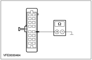
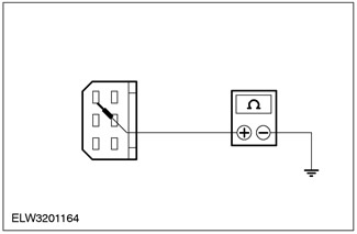
A9: CHECKING THE DUAL PRESSURE SWITCH |
|
|
1Enter the OFF position. |
|
|
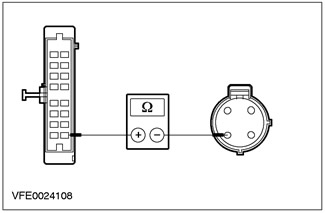
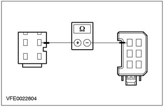
2Measure the resistance between pins 2 and 4 of the C882 dual pressure switch connector, element side. |
|
• Is the resistance registered less than 2 ohms? |
|
|
→ Yes |
|
|
LOCATE and REPAIR the open in the electrical circuit between the dual pressure switch and the A/C WOT switch using the wiring diagrams. CHECK the system for proper operation. |
|
|
→ No |
|
|
CHECK the air conditioning system pressure and REPAIR as necessary. If the system pressure is correct, REPLACE the dual pressure switch. CHECK the system for proper operation. |
|
|
A10: CHECKING THE VOLTAGE AT THE A/C WIDE OPEN THROTTLE (WOT) CUT-OFF RELAY |
|
|
1Disconnect C1011 A/C WOT relay. |
|
|
2Enter the ON position. |
|

|
3Measure the voltage between pin 3 of the A/C WOT relay connector C1011, wiring harness side, and ground. |
|
• Is battery voltage registered? |
|
|
→ Yes |
|
|
Go to A11 |
|
|
→ No |
|
|
LOCATE and REPAIR the open in the electrical circuit between the A/C WOT relay and fuse F58 using the wiring diagrams. CHECK the system for proper operation. |
|
|
A11: CHECKING SUPPLY VOLTAGE AT A/C WOT RELAY |
|
|
1Measure the voltage between A/C WOT relay connector C1011 pin 1, circuit 15-FA11 (GN/YE), harness side and ground. |
|
• Is battery voltage registered? |
|
|
→ Yes |
|
|
Go to A12 |
|
|
→ No |
|
|
RESTORE power to the A/C WOT relay using the wiring diagrams. CHECK for proper system operation. |
|
|
A12: CHECKING A/C COMPRESSOR CLUTCH CIRCUIT |
|
|
1Enter the OFF position. |
|

|
2Install a 7.5A fused jumper cable between pins 3 and 5 of the A/C WOT relay connector C1011, on the wiring harness side. |
|
3Enter the ON position. |
|
|
4Check the operation of the air conditioning compressor clutch. |
|
|
• Is the air conditioning compressor clutch working? |
|
|
→ Yes |
|
|
Go to A15 |
|
|
→ No |
|
|
Go to A13 |
|
|
A13: CHECKING A/C COMPRESSOR CLUTCH SUPPLY VOLTAGE |
|
|
1Enter the OFF position. |
|
|
2Disconnect C952 A/C compressor clutch. |
|
|
3Install a 7.5A fused jumper cable between pins 3 and 5 of the A/C WOT relay connector C1011, on the wiring harness side. |
|
4Enter the ON position. |
|
|
5Measure the voltage between A/C compressor clutch connector C952 pin 1, circuit 15S-FA6 (GN/YE), harness side and ground. |
|
• Is battery voltage registered? |
|
|
→ Yes |
|
|
Go to A14 |
|
|
→ No |
|
|
LOCATE and REPAIR the open in the electrical circuit between the A/C WOT relay and the A/C compressor clutch using the wiring diagrams. CHECK the system for proper operation. |
|
|
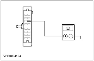
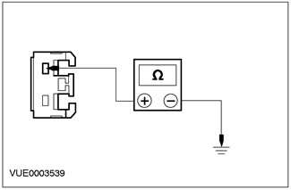
A14: CHECKING THE A/C COMPRESSOR CLUTCH GROUND CIRCUIT |
|
|
1Enter the OFF position. |
|
|
2Measure the resistance between pin 2 of the A/C compressor clutch connector C952, circuit 31-FA6 (Black), wiring harness side and ground. |
|
• Is the resistance registered less than 2 ohms? |
|
|
→ Yes |
|
|
REPLACE the air conditioning compressor clutch. CHECK the system for proper operation. |
|
|
→ No |
|
|
LOCATE and REPAIR the open in the electrical circuit between the A/C compressor clutch and ground point G56 using the wiring diagrams. CHECK for proper system operation. |
|
|
A15: CHECKING THE A/C WIDE OPEN THROTTLE (WOT) CUT-OFF RELAY |
|
|
1Check the A/C WOT relay by following the component tests described at the end of this section. |
|
|
• Is the A/C WOT relay OK? |
|
|
→ Yes |
|
|
Go to A16 |
|
|
→ No |
|
|
REPLACE the A/C WOT relay. CHECK the system for proper operation. |
|
|
A16: CHECKING POWER VOLTAGE AT A/C COMPRESSOR SWITCH |
|
|
1Enter the OFF position. |
|
|
2Disconnect C692 air conditioning compressor switch. |
|
|
3Enter the ON position. |
|
|
4Turn on the air conditioning system. |
|
|
5Turn on the heater fan. |
|
|
6Measure the voltage between pin 4 of the air conditioning compressor switch connector C692, circuit 15S-FA17 (Green/Orange), wiring harness side and ground. |
|
• Is battery voltage registered? |
|
|
→ Yes |
|
|
Go to A17 |
|
|
→ No |
|
|
Go to A24 |
|
|
A17: CHECKING A/C COMPRESSOR SWITCH |
|
|
1Enter the OFF position. |
|
|
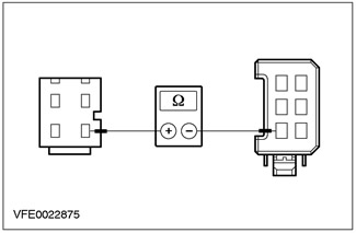
2Measure the resistance between pins 4 and 1 of connector C692 of the air conditioning compressor cycling switch, on the component side. |
|
• Is the resistance registered less than 2 ohms? |
|
|
→ Yes |
|
|
Cars manufactured before 05.99 with EEC V (60-pin): Go to A20 |
|
|
Cars manufactured before 05.99 with EEC V (104-pin): Go to A22 |
|
|
Cars manufactured since 05.99 Go to A18 |
|
|
→ No |
|
|
CHECK the refrigerant charge and ADJUST if necessary. If the refrigerant charge is correct, REPLACE the A/C compressor cycling switch. CHECK the system for proper operation. |
|
|
A18: CHECKING THE SUPPLY VOLTAGE IN THE DUAL PRESSURE SWITCH |
|
|
1Connect C692 to the air conditioning compressor switch. |
|
|
2Disconnect Dual Pressure Switch C882. |
|
|
3Enter the ON position. |
|
|
4Turn on the air conditioning system. |
|
|
5Turn on the heater fan. |
|
|
6Measure the voltage between pin 2 of dual pressure switch connector C882, circuit 15S-FA38 (green/red), wiring harness side, and ground. |
|
• Is battery voltage registered? |
|
|
→ Yes |
|
|
Go to A19 |
|
|
→ No |
|
|
LOCATE and REPAIR the open in the C circuit between the A/C compressor switch and the dual pressure switch using the wiring diagrams. CHECK for proper system operation. |
|
|
A19: CHECKING THE DUAL PRESSURE SWITCH |
|
|
1Enter the OFF position. |
|

|
2Measure the resistance between pins 2 and 4 of the C882 dual pressure switch connector, element side. |
|
• Is the resistance registered less than 2 ohms? |
|
|
→ Yes |
|
|
Vehicles with EEC V (60-pin): Go to A20 |
|
|
Vehicles with EEC V (104-pin): Go to A22 |
|
|
→ No |
|
|
CHECK the air conditioning system pressure and REPAIR as necessary. If the system pressure is correct, REPLACE the dual pressure switch. CHECK the system for proper operation. |
|
|
A20: CHECKING VOLTAGE IN PCM |
|
|
1Connect C882 dual pressure switch. |
|
|
2Disconnect C416 PCM. |
|
|
3Enter the ON position. |
|
|
4Turn on the air conditioning system. |
|
|
5Turn on the heater fan. |
|
|
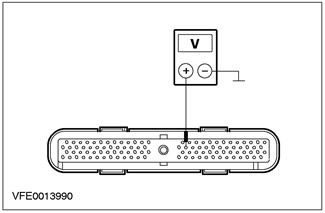
6Measure the voltage between PCM connector C416 pin 10, circuit 15S-RE18 (GN/YE), (vehicles built since 05/99): circuit 15S-RE8 (GN/YE), wiring harness side and ground. |
|
• Is battery voltage registered? |
|
|
→ Yes |
|
|
Go to A21 |
|
|
→ No |
|
|
LOCATE and REPAIR the open in the 15S-RE18 (green/yellow) or 15S-RE8 (green/yellow) circuit using the wiring diagrams. CHECK that the system is operating correctly. |
|
|
A21: CHECKING VOLTAGE IN PCM |
|
|
1Enter the OFF position. |
|
|
2Connect C1011 to A/C WOT relay. |
|
|
3Enter the ON position. |
|
|
4Measure the voltage between PCM connector C416 pin 54, circuit 31S-FA11 (BK/YE), wiring harness side and ground. |
|
• Is battery voltage registered? |
|
|
→ Yes |
|
|
CHECK the PCM and REPLACE it if necessary. CHECK the system for proper operation. |
|
|
→ No |
|
|
LOCATE and REPAIR the open in the circuit between the A/C WOT relay and the PCM using the wiring diagrams. CHECK the system for proper operation. |
|
|
A22: CHECKING VOLTAGE IN PCM |
|
|
1Connect C882 dual pressure switch. |
|
|
2Disconnect C415 PCM. |
|
|
3Enter the ON position. |
|
|
4Turn on the air conditioning system. |
|
|
5Turn on the heater fan. |
|
|
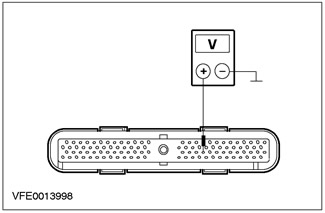
6Measure the voltage between PCM connector C415 pin 41, circuit 15S-RE18 (GN/YE), (vehicles built since 05/99): circuit 15S-RE8 (GN/YE), wiring harness side and ground. |
|
• Is battery voltage registered? |
|
|
→ Yes |
|
|
Go to A23 |
|
|
→ No |
|
|
LOCATE and REPAIR the open in the 15S-RE18 (green/yellow) or 15S-RE8 (green/yellow) circuit using the wiring diagrams. CHECK that the system is operating correctly. |
|
|
A23: CHECKING VOLTAGE IN PCM |
|
|
1Enter the OFF position. |
|
|
2Connect C1011 to A/C WOT relay. |
|
|
3Enter the ON position. |
|
|
4Measure the voltage between PCM connector C415 pin 69, circuit 31S-FA11 (BK/YE), wiring harness side and ground. |
|
• Is battery voltage registered? |
|
|
→ Yes |
|
|
CHECK the PCM and REPLACE it if necessary. CHECK the system is operating correctly. |
|
|
→ No |
|
|
LOCATE and REPAIR the open in the circuit between the A/C WOT relay and the PCM using the wiring diagrams. CHECK the system for proper operation. |
|
|
A24: CHECKING THE ELECTRICAL CIRCUIT BETWEEN THE HEATER CONTROL MODULE AND THE A/C COMPRESSOR SWITCH |
|
|
1Enter the OFF position. |
|
|
2Disconnect the C380 Heater Control Module. |
|
|
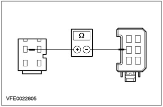
3Measure the resistance between pin 9 of the heater control module connector C380, circuit 15S-FA17 (GN/OG), wire harness side and pin 4 of the A/C compressor switch connector C692, circuit 15S-FA17 (GN/OG), wire harness side. |
|
• Is the resistance registered less than 2 ohms? |
|
|
→ Yes |
|
|
Go to A25 |
|
|
→ No |
|
|
LOCATE and REPAIR the open in the 15S-FA17 (Green/Orange) circuit between the Heater Control Module and the A/C Compressor Switch using the Wiring Diagrams. CHECK for proper system operation. |
|
|
A25: CHECKING VOLTAGE IN THE HEATER CONTROL MODULE |
|
|
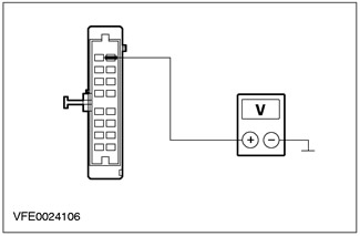
1Measure the voltage between pin 8 of the heater control module connector C380, circuit 29-FA13 (orange), wiring harness side, and ground. |
|
• Is battery voltage registered? |
|
|
→ Yes |
|
|
Go to A26 |
|
|
→ No |
|
|
LOCATE and REPAIR the open in the electrical circuit between fuse F36 and the heater control module using the wiring diagrams. CHECK the system for proper operation. |
|
|
A26: CHECKING VOLTAGE IN THE HEATER CONTROL MODULE |
|
|
1Enter the ON position. |
|
|
2Measure the voltage between pin 10 of the heater control module connector C380 and ground. |
|
• Is battery voltage registered? |
|
|
→ Yes |
|
|
Go to A27 |
|
|
→ No |
|
|
LOCATE and REPAIR the open in the electrical circuit between the heater control module and fuse F58 using the wiring diagrams. CHECK the system for proper operation. |
|
|
A27: CHECKING VOLTAGE IN THE HEATER CONTROL MODULE |
|
|
1Enter the START position. |
|
|
2Measure the voltage between pin 11 of the heater control module connector C380, wiring harness side, and ground. |
|
• Is battery voltage registered? |
|
|
→ Yes |
|
|
Go to A28 |
|
|
→ No |
|
|
LOCATE and REPAIR the open in the electrical circuit between the heater control module and the engine run relay using the wiring diagrams. CHECK the system for proper operation. |
|
|
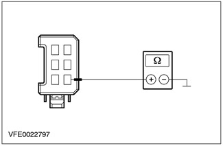
A28: CHECKING THE HEATER CONTROL MODULE GROUND CIRCUIT |
|
|
1Enter the OFF position. |
|
|
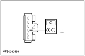
2Measure the resistance between pin 12 of the heater control module connector C380, circuit 91-FA13 (black/orange), wiring harness side, and ground. |
|
• Is the resistance registered less than 2 ohms? |
|
|
→ Yes |
|
|
Go to A29 |
|
|
→ No |
|
|
LOCATE and REPAIR the open in the electrical circuit between the heater control module and ground point G41 using the wiring diagrams. CHECK for proper system operation. |
|
|
A29: CHECKING THE ELECTRICAL CIRCUIT BETWEEN THE HEATER CONTROL MODULE AND THE HEATER BLOWER SWITCH |
|
|
1Set the heater fan switch to low speed. |
|
|
2Measure the resistance between pin 6 of the heater control module connector C380, circuit 31S-FA26 (black/red), wiring harness side, and ground. |
|
• Is the resistance registered less than 2 ohms? |
|
|
→ Yes |
|
|
CHECK and if necessary REPLACE the heater control module. CHECK the system is operating correctly. |
|
|
→ No |
|
|
LOCATE and REPAIR the open in circuit 31S-FA26 (BK/RD) between the Heater Control Module and the Heater Blower Switch using the Wiring Diagrams. CHECK for proper system operation. |
|
PINPOINT TEST B: HEATER FAN, PARTIALLY/FULLY NOT WORKING
|
STATES |
DETAILS/RESULTS/ACTIONS |
|
B1: DETERMINING THE CONDITIONS UNDER WHICH A FAILURE OCCURRES |
|
|
1Enter the ON position. |
|
|
2Cycle the heater fan switch through all three positions. |
|
|
• The heater fan motor does not operate in all three switch positions? |
|
|
→ Yes |
|
|
Go to B2 |
|
|
→ No |
|
|
Go to B10 |
|
|
B2: CHECKING FUSE F64 |
|
|
1Enter the OFF position. |
|
|
2CHECK Fuse F64 (BJB). |
|
|
• Is the fuse good? |
|
|
→ Yes |
|
|
Go to B3 |
|
|
→ No |
|
|
REPLACE fuse F64 (30A). CHECK the system for proper operation. If the fuse blows again, LOCATE and REPAIR the short to ground using the wiring diagrams. |
|
|
B3: CHECKING THE VOLTAGE IN FUSE F64 |
|
|
1Connect Fuse F64 (BJB). |
|
|
2Enter the ON position. |
|
|
3Check the voltage in the electrical circuit between fuse F64 (30 A) and ground. |
|
|
• Is battery voltage registered? |
|
|
→ Yes |
|
|
Go to B4 |
|
|
→ No |
|
|
RESTORE power to fuse F64 using the wiring diagrams. CHECK that the system is operating correctly. |
|
|
B4: CHECKING THE VOLTAGE IN THE HEATER FAN MOTOR |
|
|
1Enter the OFF position. |
|
|
2Disconnect C789 heater blower motor. |
|
|
3Enter the ON position. |
|
|
4Measure the voltage between pin 1 of the heater blower motor connector C789, circuit 15-FA18 (green/orange), wiring harness side, and ground. |
|
• Is battery voltage registered? |
|
|
→ Yes |
|
|
Go to B5 |
|
|
→ No |
|
|
LOCATE and REPAIR the open in the electrical circuit between the heater blower motor and fuse F64 using the wiring diagrams. CHECK the correct operation of the system. |
|
|
B5: CHECKING THE ELECTRICAL GROUND CIRCUIT OF THE HEATER ELECTRIC FAN |
|
|
1Enter the OFF position. |
|
|
2Set the heater fan switch to "maximum". |
|
|
3Measure the resistance between pin 2 of the heater blower motor connector C789, circuit 31S-FA18 (black/red), wiring harness side, and ground. |
|
• Is the resistance registered less than 2 ohms? |
|
|
→ Yes |
|
|
REPLACE the heater blower. CHECK the system for proper operation. |
|
|
→ No |
|
|
Cars manufactured before 01.00: Go to B6 |
|
|
Cars manufactured since 01.00: Go to B8 |
|
|
B6: CHECKING THE ELECTRICAL CIRCUIT BETWEEN THE HEATER FAN MOTOR AND THE HEATER FAN SWITCH |
|
|
1Disconnect C469 heater fan switch. |
|

|
2Measure the resistance between pin 2 of connector C789 heater blower motor, circuit 31S-FA18 (BK/RED), wiring harness side and pin 4 of connector C469 heater blower switch, circuit 31S-FA33 (BK/ORN), wiring harness side. |
|
• Is the resistance registered less than 2 ohms? |
|
|
→ Yes |
|
|
Go to B7 |
|
|
→ No |
|
|
LOCATE and REPAIR the open in the 31S-FA18 (black/red) circuit between the heater blower motor and solder joint S24 using the wiring diagrams. CHECK the system for proper operation. |
|
|
B7: CHECKING THE HEATER FAN SWITCH GROUND CIRCUIT |
|
|
1Measure the resistance between pin 6 of the heater blower switch connector C469, circuit 31-FA25 (black), wiring harness side and ground. |
|
• Is the resistance registered less than 2 ohms? |
|
|
→ Yes |
|
|
REPLACE the heater fan switch. CHECK the system for proper operation. |
|
|
→ No |
|
|
LOCATE and REPAIR the open in the electrical circuit between the heater blower switch and ground point G14 using the wiring diagrams. CHECK the system for proper operation. |
|
|
B8: CHECKING THE ELECTRICAL CIRCUIT BETWEEN THE HEATER FAN MOTOR AND THE HEATER FAN SWITCH |
|
|
1Disconnect C469 heater fan switch. |
|

|
2Measure the resistance between pin 2 of connector C789 heater blower motor, circuit 31S-FA18 (BK/RED), wiring harness side and pin 6 of connector C469 heater blower switch, circuit 31S-FA33 (BK/ORN), wiring harness side. |
|
• Is the resistance registered less than 2 ohms? |
|
|
→ Yes |
|
|
Go to B9 |
|
|
→ No |
|
|
LOCATE and REPAIR the open in the 31S-FA18 (black/red) circuit between the heater blower motor and solder joint S24 using the wiring diagrams. CHECK the system for proper operation. |
|
|
B9: CHECKING THE HEATER FAN SWITCH GROUND CIRCUIT |
|
|
1Measure the resistance between pin 2 of the heater blower switch connector C469, circuit 31-FA25 (black), wiring harness side and ground. |
|
• Is the resistance registered less than 2 ohms? |
|
|
→ Yes |
|
|
REPLACE the heater fan switch. CHECK the system for proper operation. |
|
|
→ No |
|
|
LOCATE and REPAIR the open in the electrical circuit between the heater blower switch and ground point G14 using the wiring diagrams. CHECK the system for proper operation. |
|
|
B10: DETERMINING THE CONDITIONS UNDER WHICH A FAULT OCCURRS |
|
|
1Set the heater fan switch to "maximum". |
|
|
• Heater fan motor not working? |
|
|
→ Yes |
|
|
Cars manufactured before 01.00: Go to B11 |
|
|
Cars manufactured since 01.00: Go to B12 |
|
|
→ No |
|
|
Cars manufactured before 01.00: Go to B13 |
|
|
Cars manufactured since 01.00: Go to B18 |
|
|
B11: CHECKING THE ELECTRICAL CIRCUIT BETWEEN THE HEATER FAN MOTOR AND THE HEATER FAN SWITCH |
|
|
1Enter the OFF position. |
|
|
2Disconnect C469 heater fan switch. |
|
|
3Disconnect C789 heater blower motor. |
|
|
4Measure the resistance between pin 2 of connector C789 heater blower motor, circuit 31S-FA18 (BK/RED), wiring harness side and pin 4 of connector C469 heater blower switch, circuit 31S-FA33 (BK/ORN), wiring harness side. |
|
• Is the resistance registered less than 2 ohms? |
|
|
→ Yes |
|
|
REPLACE the heater fan switch. CHECK the system for proper operation. |
|
|
→ No |
|
|
LOCATE and REPAIR the open in circuit 31S-FA33 (Black/Orange) between the heater blower switch and solder joint S24 using the wiring diagrams. CHECK for proper system operation. |
|
|
B12: CHECKING THE ELECTRICAL CIRCUIT BETWEEN THE HEATER FAN MOTOR AND THE HEATER FAN SWITCH |
|
|
1Enter the OFF position. |
|
|
2Disconnect C469 heater fan switch. |
|
|
3Disconnect C789 heater blower motor. |
|
|
4Measure the resistance between pin 2 of connector C789 heater blower motor, circuit 31S-FA18 (BK/RED), wiring harness side and pin 6 of connector C469 heater blower switch, circuit 31S-FA33 (BK/ORN), wiring harness side. |
|
• Is the resistance registered less than 2 ohms? |
|
|
→ Yes |
|
|
REPLACE the heater fan switch. CHECK the system for proper operation. |
|
|
→ No |
|
|
LOCATE and REPAIR the open in circuit 31S-FA33 (Black/Orange) between the heater blower switch and solder joint S24 using the wiring diagrams. CHECK for proper system operation. |
|
|
B13: CHECKING THE HEATER FAN SWITCH |
|
|
1Enter the OFF position. |
|
|
2Disconnect C469 heater fan switch. |
|
|
3Enter the ON position. |
|
|
4Measure the voltage between pin 1 of the heater blower switch connector C469, circuit 31S-FA32 (BLK/BU), wiring harness side, and ground. |
|
5Measure the voltage between pin 2 of the heater blower switch connector C469, circuit 31S-FA31 (BK/YE), wiring harness side and ground. |
|
|
6Measure the voltage between pin 3 of the heater blower switch connector C469, circuit 31S-FA30 (BK/WH), wiring harness side and ground. |
|
|
• Is battery voltage registered during all measurements? |
|
|
→ Yes |
|
|
REPLACE the heater fan switch. CHECK the system for proper operation. |
|
|
→ No |
|
|
Go to B14 |
|
|
B14: CHECKING THE ELECTRICAL CIRCUIT BETWEEN THE HEATER FAN MOTOR AND THE HEATER FAN VARIABLE RESISTOR. |
|
|
1Enter the OFF position. |
|
|
2Disconnect C470 heater blower variable resistor. |
|
|
3Enter the ON position. |
|
|
4Measure the voltage between pin 1 of the C470 connector of the variable resistor of the heater electric fan, electrical circuit 31S-FA1 (black/blue), on the wiring harness side, and ground. |
|
• Is battery voltage registered? |
|
|
→ Yes |
|
|
Go to B15 |
|
|
→ No |
|
|
LOCATE and REPAIR the open in the 31S-FA1 (BLK/BLUE) circuit between the heater blower variable resistor and solder joint S24 using the Wiring Diagrams. CHECK for proper system operation. |
|
|
B15: CHECK CIRCUIT BETWEEN HEATER BLOWER VARIABLE RESISTOR AND HEATER BLOWER SWITCH |
|
|
1Enter the OFF position. |
|
|
2Measure the resistance between pin 4 of connector C470 of the heater blower motor variable resistor, circuit 31S-FA32 (BLK/BU), wiring harness side and pin 1 of connector C469 of the heater blower switch, circuit 31S-FA32 (BLK/BU), wiring harness side. |
|
• Is the resistance registered less than 2 ohms? |
|
|
→ Yes |
|
|
Go to B16 |
|
|
→ No |
|
|
LOCATE and REPAIR the open in the 31S-FA32 (BLK/BLUE) circuit between the heater blower motor variable resistor and the heater blower switch using the wiring diagrams. CHECK for proper system operation. |
|
|
B16: CHECK CIRCUIT BETWEEN HEATER FAN VARIABLE RESISTOR AND HEATER FAN SWITCH |
|
|
1Measure the resistance between pin 2 of connector C470 of the heater blower motor variable resistor, circuit 31S-FA31 (BK/YE), wiring harness side and pin 2 of connector C469 of the heater blower switch, circuit 31S-FA31 (BK/YE), wiring harness side. |
|
• Is the resistance registered less than 2 ohms? |
|
|
→ Yes |
|
|
Go to B17 |
|
|
→ No |
|
|
LOCATE and REPAIR the open in the 31S-FA31 (BK/YEL) circuit between the heater blower motor variable resistor and the heater blower switch using the wiring diagrams. CHECK for proper system operation. |
|
|
B17: CHECK CIRCUIT BETWEEN HEATER BLOWER VARIABLE RESISTOR AND HEATER BLOWER SWITCH |
|
|
1Measure the resistance between pin 3 of the heater blower motor variable resistor connector C470, circuit 31S-FA30 (BK/WH), wiring harness side and pin 3 of the heater blower motor switch connector C469, circuit 31S-FA30 (BK/WH), wiring harness side. |
|
• Is the resistance registered less than 2 ohms? |
|
|
→ Yes |
|
|
REPLACE the heater blower motor variable resistor. CHECK the system for proper operation. |
|
|
→ No |
|
|
LOCATE and REPAIR the open in the 31S-FA30 (BK/YEL) circuit between the heater blower motor variable resistor and the heater blower switch using the wiring diagrams. CHECK for proper system operation. |
|
|
B18: CHECKING THE HEATER FAN SWITCH |
|
|
1Enter the OFF position. |
|
|
2Disconnect C469 heater fan switch. |
|
|
3Enter the ON position. |
|
|
4Measure the voltage between pin 5 of the heater blower switch connector C469, circuit 31S-FA32 (BLK/BU), wiring harness side, and ground. |
|
5Measure the voltage between pin 3 of the heater blower switch connector C469, circuit 31S-FA31 (BK/YE), wiring harness side and ground. |
|
|
6Measure the voltage between pin 1 of the heater blower switch connector C469, circuit 31S-FA30 (BK/WH), wiring harness side and ground. |
|
|
• Is battery voltage registered during all measurements? |
|
|
→ Yes |
|
|
REPLACE the heater fan switch. CHECK the system for proper operation. |
|
|
→ No |
|
|
Go to B19 |
|
|
B19: CHECK THE ELECTRICAL CIRCUIT BETWEEN THE HEATER FAN MOTOR AND THE HEATER FAN VARIABLE RESISTOR. |
|
|
1Enter the OFF position. |
|
|
2Disconnect C470 heater blower variable resistor. |
|
|
3Enter the ON position. |
|

|
4Measure the voltage between pin 1 of connector C470 of the heater blower motor variable resistor, circuit 31S-FA1 (black/blue) (from 08/2000 circuit 31S-FA33 (black/orange)), wiring harness side, and ground. |
|
• Is battery voltage registered? |
|
|
→ Yes |
|
|
Go to B20 |
|
|
→ No |
|
|
LOCATE and REPAIR the open in the electrical circuit between solder joint S24 and the heater blower variable resistor using the wiring diagrams. CHECK the system for proper operation. |
|
|
B20: CHECK CIRCUIT BETWEEN HEATER BLOWER VARIABLE RESISTOR AND HEATER BLOWER SWITCH |
|
|
1Enter the OFF position. |
|
|
2Measure the resistance between pin 4 of connector C470 of the heater blower motor variable resistor, circuit 31S-FA32 (BLK/BU), wiring harness side and pin 5 of connector C469 of the heater blower switch, circuit 31S-FA32 (BLK/BU), wiring harness side. |
|
• Is the resistance registered less than 2 ohms? |
|
|
→ Yes |
|
|
Go to B21 |
|
|
→ No |
|
|
LOCATE and REPAIR the open in the 31S-FA32 (BLK/BLUE) circuit between the heater blower motor variable resistor and the heater blower switch using the wiring diagrams. CHECK for proper system operation. |
|
|
B21: CHECK CIRCUIT BETWEEN HEATER FAN VARIABLE RESISTOR AND HEATER FAN SWITCH |
|
|
1Measure the resistance between pin 3 of connector C470 of the heater blower motor variable resistor, circuit 31S-FA31 (BK/YEL), wiring harness side, and pin 2 of connector C469 of the heater blower switch, circuit 31S-FA31 (BK/YEL), wiring harness side. |
|
• Is the resistance registered less than 2 ohms? |
|
|
→ Yes |
|
|
Go to B22 |
|
|
→ No |
|
|
LOCATE and REPAIR the open in the 31S-FA31 (BK/YEL) circuit between the heater blower motor variable resistor and the heater blower switch using the wiring diagrams. CHECK for proper system operation. |
|
|
B22: CHECK CIRCUIT BETWEEN HEATER FAN VARIABLE RESISTOR AND HEATER FAN SWITCH |
|
|
1Measure the resistance between pin 1 of connector C470 of the heater blower motor variable resistor, circuit 31S-FA30 (BK/WH), wiring harness side and pin 3 of connector C469 of the heater blower switch, circuit 31S-FA30 (BK/WH), wiring harness side. |
|
• Is the resistance registered less than 2 ohms? |
|
|
→ Yes |
|
|
REPLACE the heater blower motor variable resistor. CHECK the system for proper operation. |
|
|
→ No |
|
|
LOCATE and REPAIR the open in the 31S-FA30 (BK/YEL) circuit between the heater blower motor variable resistor and the heater blower motor switch using the wiring diagrams. CHECK for proper system operation. |
|
PINPOINT TEST C: FAN MOTOR RUNS CONTINUOUSLY
|
STATES |
DETAILS/RESULTS/ACTIONS |
|
C1: CHECKING THE HEATER FAN SWITCH |
|
|
1Enter the OFF position. |
|
|
2Disconnect C469 heater fan switch. |
|
|
3Enter the ON position. |
|
|
4Check the operation of the heater electric fan. |
|
|
• Does the heater fan motor run continuously? |
|
|
→ Yes |
|
|
Go to C2 |
|
|
→ No |
|
|
REPLACE the heater fan switch. CHECK the system for proper operation. |
|
|
C2: CHECK THE CIRCUIT TO THE HEATER FAN VARIABLE RESISTOR |
|
|
1Enter the OFF position. |
|
|
2Disconnect C470 heater blower variable resistor. |
|
|
3Enter the ON position. |
|
|
4Check the operation of the heater electric fan. |
|
|
• Does the heater fan motor run continuously? |
|
|
→ Yes |
|
|
CHECK all electrical circuits connected to solder point S24 for short to ground using the wiring diagrams and REPAIR. CHECK proper system operation. |
|
|
→ No |
|
|
CHECK all electrical circuits between the heater blower variable resistor and the heater blower switch for short to ground using the wiring diagrams and REPAIR. CHECK proper system operation. |
|
PINPOINT TEST D: AIR RECIRCULATION FLAP NOT WORKING CORRECTLY
|
STATES |
DETAILS/RESULTS/ACTIONS |
|
D1: DETERMINING THE MODEL VARIANT |
|
|
1Determine the model option. |
|
|
• Was the car manufactured before 05.99? |
|
|
→ Yes |
|
|
Go to D2 |
|
|
→ No |
|
|
Go to D8 |
|
|
D2: CHECKING THE GROUNDING CIRCUIT OF THE AIR RECIRCULATION FLAP POSITIONING MOTOR |
|
|
1Enter the OFF position. |
|
|
2Disconnect C375 Air Recirculation Damper Positioning Motor. |
|
|
3Measure the resistance between pin 4 of the air recirculation flap positioning motor connector C375, wiring harness side, and ground. |
|
• Is the resistance registered less than 2 ohms? |
|
|
→ Yes |
|
|
Go to D3 |
|
|
→ No |
|
|
LOCATE and REPAIR the open in the electrical circuit between the air recirculation flap positioning motor and ground point G41 using the wiring diagrams. CHECK the system for proper operation. |
|
|
D3: CHECKING THE ELECTRICAL CIRCUIT BETWEEN THE HEATER CONTROL MODULE AND THE AIR RECIRCULATION FLAP POSITIONING MOTOR |
|
|
1Disconnect the C380 Heater Control Module. |
|
|
2Measure the resistance between pin 16 of the heater control module connector C380, circuit 33-FA76 (YE/BU), wiring harness side and pin 1 of the recirculated air flap servo motor connector C375, circuit 33-FA76 (YE/BU) (RHD: pin 6, circuit 32-FA76 (WH/BU)), wiring harness side. |
|
• Is the resistance registered less than 2 ohms? |
|
|
→ Yes |
|
|
Go to D4 |
|
|
→ No |
|
|
LOCATE and REPAIR the open in circuit 33-FA76 (YE/BL) or circuit 32-FA76 (WH/BL) between the heater control module and the recirculated air door positioning motor using the Wiring Diagrams. CHECK for proper system operation. |
|
|
D4: CHECKING THE ELECTRICAL CIRCUIT BETWEEN THE HEATER CONTROL MODULE AND THE AIR RECIRCULATION FLAP POSITIONING MOTOR |
|

|
1Measure the resistance between pin 14 of the heater control module connector C380, circuit 32-FA76 (WH/BU), wiring harness side and pin 6 of the recirculated air flap servo motor connector C375, circuit 32-FA76 (WH/BU) (right-hand drive: pin 1, circuit 33-FA76 (YE/BU)), wiring harness side. |
|
• Is the resistance registered less than 2 ohms? |
|
|
→ Yes |
|
|
Go to D5 |
|
|
→ No |
|
|
LOCATE and REPAIR the open in circuit 32-FA76 (WH/BU) or circuit 33-FA76 (YE/BU) between the heater control module and the recirculated air door positioning motor using the Wiring Diagrams. CHECK for proper system operation. |
|
|
D5: CHECKING THE ELECTRICAL CIRCUIT BETWEEN THE AIR RECIRCULATION FLAP POSITIONING MOTOR AND THE HEATER CONTROL MODULE |
|
|
1Measure the resistance between pin 4 of the heater control module connector C380, circuit 91S-FA90 (BK/GN), wiring harness side and pin 3 of the recirculated air flap positioning motor C375, circuit 91S-FA90 (BK/GN), wiring harness side. |
|
• Is the resistance registered less than 2 ohms? |
|
|
→ Yes |
|
|
Go to D6 |
|
|
→ No |
|
|
LOCATE and REPAIR the open in circuit 91S-FA90 (Black/Green) between the heater control module and the recirculated air flap positioning motor using the Wiring Diagrams. CHECK for proper system operation. |
|
|
D6: CHECKING THE HEATER CONTROL MODULE |
|
|
NOTE:If the air distribution control switch is set to the defog/defrost position, the air recirculation mode cannot be switched on. |
|
|
1Connect the C380 Heater Control Module. |
|
|
2Enter the ON position. |
|
|
3Turn on air recirculation. |
|
|
4Measure the voltage between pins 1 and 6 of the air recirculation flap positioning motor connector C375, wiring harness side. |
|
• Is the voltage registered at least 10V? |
|
|
→ Yes |
|
|
Go to D7 |
|
|
→ No |
|
|
CHECK and REPLACE the heater control module if necessary. CHECK that the system is operating correctly. |
|
|
D7: CHECKING THE HEATER CONTROL MODULE |
|
|
1Turn off air recirculation. |
|

|
2Measure the voltage again between pins 1 and 6 of the air recirculation flap positioning motor connector C375, wiring harness side. |
|
• Has the voltage polarity changed? |
|
|
→ Yes |
|
|
CHECK the air recirculation flap for freedom of movement. If the air recirculation flap is mechanically OK, REPLACE the air recirculation flap positioning motor. CHECK the system for proper operation. |
|
|
→ No |
|
|
CHECK and if necessary REPLACE the heater control module. CHECK the system is operating correctly. |
|
|
D8: CHECKING THE GROUNDING CIRCUIT OF THE AIR RECIRCULATION FLAP POSITIONING MOTOR |
|
|
1Enter the OFF position. |
|
|
2Disconnect C375 Air Recirculation Damper Positioning Motor. |
|
|
3Measure the resistance between pin 3 of the air recirculation flap positioning motor connector C375, wiring harness side, and ground. |
|
• Is the resistance registered less than 2 ohms? |
|
|
→ Yes |
|
|
Go to D9 |
|
|
→ No |
|
|
LOCATE and REPAIR the open in the electrical circuit between the air recirculation flap positioning motor and ground point G41 using the wiring diagrams. CHECK the system for proper operation. |
|
|
D9: CHECKING THE ELECTRICAL CIRCUIT BETWEEN THE HEATER CONTROL MODULE AND THE AIR RECIRCULATION FLAP POSITIONING MOTOR |
|
|
1Disconnect the C380 Heater Control Module. |
|

|
2Measure the resistance between pin 16 of the heater control module connector C380, circuit 33-FA76 (YE/BU), wiring harness side and pin 6 of the recirculated air flap servo motor connector C375, circuit 33-FA76 (YE/BU) (RHD: pin 1, circuit 32-FA76 (WH/BU)), wiring harness side. |
|
• Is the resistance registered less than 2 ohms? |
|
|
→ Yes |
|
|
Go to D10 |
|
|
→ No |
|
|
LOCATE and REPAIR the open in circuit 33-FA76 (YE/BL) or circuit 32-FA76 (WH/BL) between the heater control module and the recirculated air door positioning motor using the Wiring Diagrams. CHECK for proper system operation. |
|
|
D10: CHECKING THE ELECTRICAL CIRCUIT BETWEEN THE HEATER CONTROL MODULE AND THE AIR RECIRCULATION FLAP POSITIONING MOTOR |
|
|
1Measure the resistance between pin 14 of the heater control module connector C380, circuit 32-FA76 (WH/BU), wiring harness side and pin 1 of the recirculated air flap servo motor connector C375, circuit 32-FA76 (WH/BU) (right-hand drive: pin 6, circuit 33-FA76 (YE/BU)), wiring harness side. |
|
• Is the resistance registered less than 2 ohms? |
|
|
→ Yes |
|
|
Go to D11 |
|
|
→ No |
|
|
LOCATE and REPAIR the open in circuit 32-FA76 (WH/BU) or circuit 33-FA76 (YE/BU) between the heater control module and the recirculated air door positioning motor using the Wiring Diagrams. CHECK for proper system operation. |
|
|
D11: CHECKING THE ELECTRICAL CIRCUIT BETWEEN THE AIR RECIRCULATION FLAP POSITIONING MOTOR AND THE HEATER CONTROL MODULE |
|
|
1Measure the resistance between pin 4 of the recirculated air flap servo motor C375, circuit 91S-FA90 (BK/GN), wiring harness side and pin 4 of the heater control module C380, circuit 91S-FA90 (BK/GN), wiring harness side. |
|
• Is the resistance registered less than 2 ohms? |
|
|
→ Yes |
|
|
Go to D12 |
|
|
→ No |
|
|
LOCATE and REPAIR the open in circuit 91S-FA90 (Black/Green) between the heater control module and the recirculated air flap positioning motor using the Wiring Diagrams. CHECK for proper system operation. |
|
|
D12: CHECKING THE HEATER CONTROL MODULE |
|
|
NOTE:If the air distribution control switch is set to the defog/defrost position, the air recirculation mode cannot be switched on. |
|
|
1Connect the C380 Heater Control Module. |
|
|
2Enter the ON position. |
|
|
3Turn on air recirculation. |
|

|
4Measure the voltage between pins 1 and 6 of the air recirculation flap positioning motor connector C375, wiring harness side. |
|
• Is the voltage registered at least 10V? |
|
|
→ Yes |
|
|
Go to D13 |
|
|
→ No |
|
|
CHECK and if necessary REPLACE the heater control module. CHECK the system is operating correctly. |
|
|
D13: CHECKING THE HEATER CONTROL MODULE |
|
|
1Turn off air recirculation. |
|

|
2Measure the voltage again between pins 1 and 6 of the air recirculation flap positioning motor connector C375, wiring harness side. |
|
• Has the voltage polarity changed? |
|
|
→ Yes |
|
|
CHECK the air recirculation flap for freedom of movement. If the air recirculation flap is mechanically OK, REPLACE the air recirculation flap positioning motor. CHECK the system for proper operation. |
|
|
→ No |
|
|
CHECK and if necessary REPLACE the heater control module. CHECK the system is operating correctly. |
|
Element checks
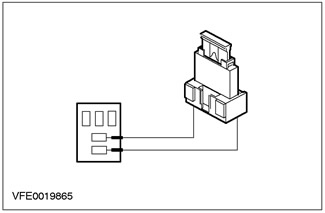
Wide Open Throttle (WOT) Air Conditioning Shutdown Relay.
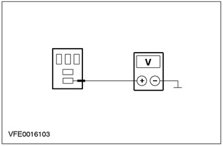
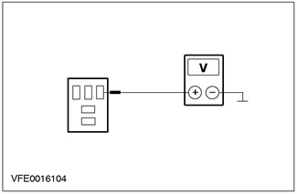
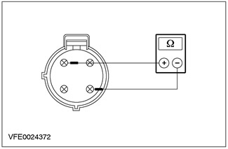
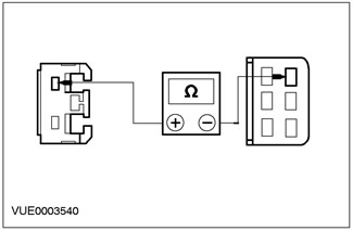
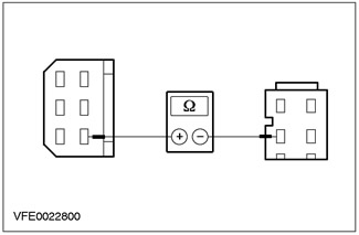
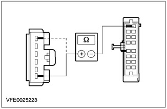
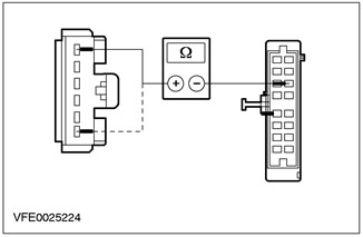
1. Check the normally open contact in the non-switching state.
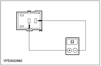
- Measure the resistance between pins 3 and 5 of the relay, on the element side.
- Is the resistance registered greater than 10 kOhm? If yes, go to step 2. If no, replace the relay.
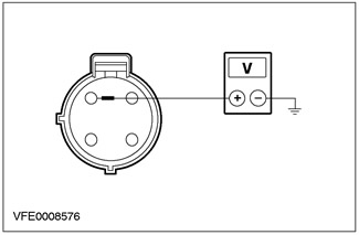
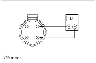
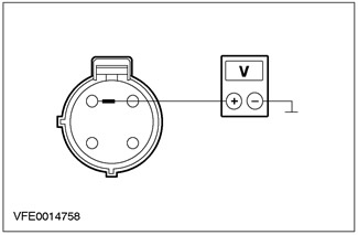
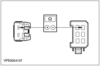
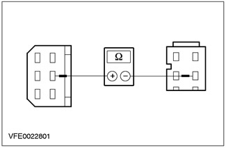
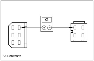
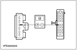
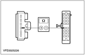
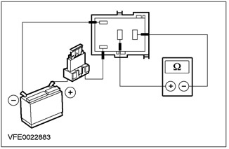
2. Check the normally open contact in the switching state.
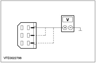
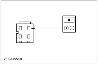
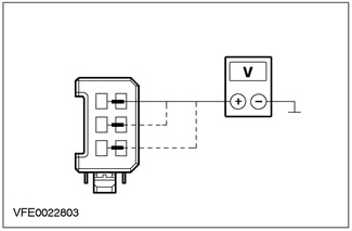
- Using a 1 Amp fused test lead, connect relay pin 1, cell side, to the positive battery terminal.
- Using a test lead, connect pin 2 of the relay, on the cell side, to the negative terminal of the battery.
- Measure the resistance between pins 3 and 5 of the relay, on the element side.
- Is the resistance registered less than 2 ohms? If yes, the relay is OK. If no, REPLACE the relay.
The article was taken in its entirety from the specified website FORDBOOK.RU