Disassembly
All cars
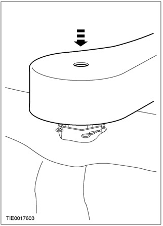
1. Remove the head restraint.
2. Detach the plastic fastening strip from the base of the seatback.
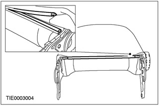
3.
CAUTION: To avoid damaging the lumbar support adjustment mechanism, apply even pressure to opposite sides of the handwheel.
NOTE: Vehicles equipped with a head restraint have a console for the lumbar support adjustment mechanism.
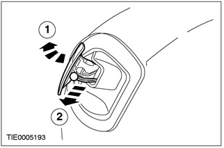
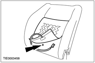
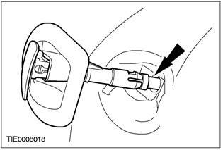
Remove the lumbar support mechanism (in the presence of).
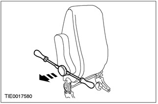
4.
NOTE: Do not remove retaining ring.
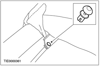
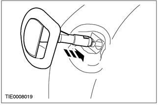
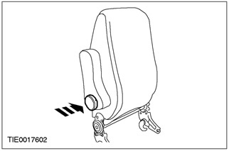
Remove armrest (in the presence of).
- 1. Move boot to access retaining ring.
- 2. Release the retaining ring.
- 3. Remove the armrest.
3-door options
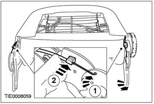
5. Disconnect the seatback lock lever cables at the seatback base.
- 1. Disconnect the outer cables from the seat frame.
- 2. Disconnect the lock lever inner cable.
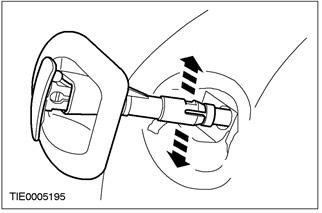
6. Disconnect the seat back lock inner cable.
- 1. Raise the lock lever.
- 2. Disconnect the lock lever inner cable.
7. Disconnect the seat back lock lever housing.
- 1. Using a suitable screwdriver, release the locking tab.
- 2. Detach the housing from the seatback frame.
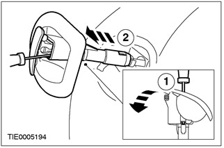
8. Remove the seat back lock lever housing.
- Disconnect the lock lever outer cable from the housing.
9. Remove the trim of the seat back lock lever.

All cars
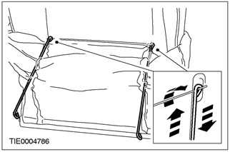
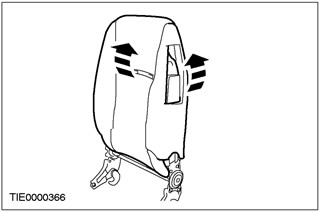
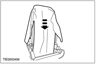
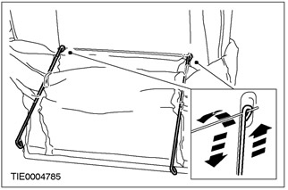
10. Roll up the seat cover to the top of the seat back to access the side tension bars.
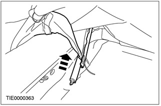
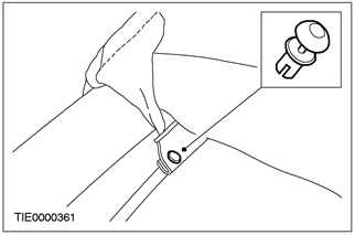
11. Disconnect the lower ends of the side tension rods.
12. Roll the seat cover up and down on the seatback.
13. Disconnect the top ends of the side tension rods.
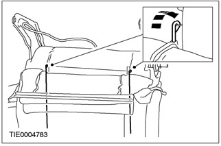
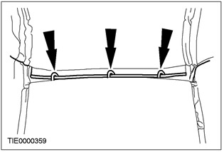
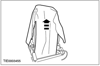
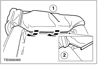
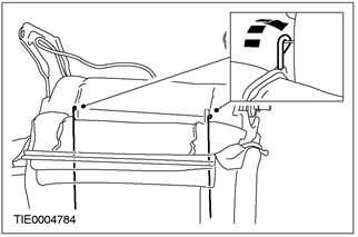
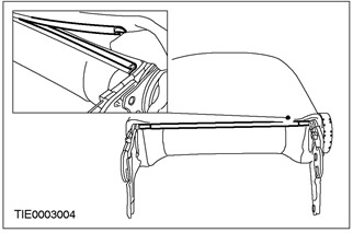
14. Roll up the seat cover over the top of the seat back frame to access the upper spring frame.
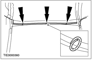
15. Cut the bent rings securing the seat cover to the top edge of the spring frame assembly.
Vehicles with side airbags
16.
WARNING: Do not reuse the plastic mounting rivet. Always use a new rivet from the service kit. Failure to heed this warning may make it difficult to deploy the airbag and cause injury.
Remove the side airbag deployer bushing retainer.
- Remove and discard the black plastic factory rivet.
17.
WARNING: Do not attempt to separate the plastic fastening strips in any other way than described. Failure to heed this warning may make it difficult to deploy the airbag and cause injury
Disengage the plastic fastening strips holding the side airbag deployment bushing
All cars
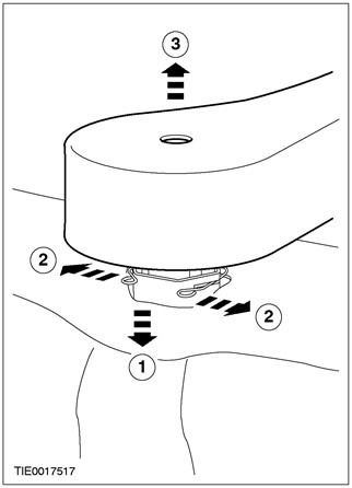
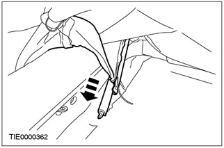
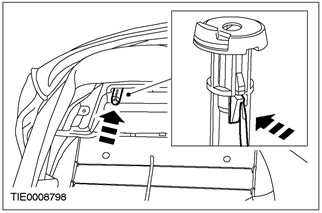
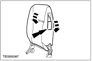
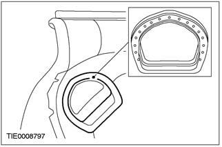
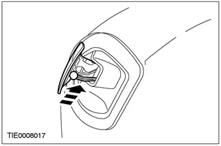
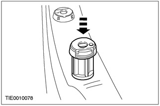
18. Remove the guide tubes of the head restraint.
- Using a suitable screwdriver, release the locking tab.
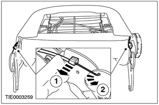
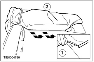
19. Detach the seat cover from the top of the seat frame.
- 1. Detach the plastic fastening strip.
- 2. Remove the seat cover.
20. Remove the side tension rods from the seat cover if a new seat cover is being installed.
21. Remove seat back foam and heater mat (in the presence of).
22.
CAUTION: Be sure to mark the exact position of the anti-creak mat on the seat frame.
Remove the anti-squeak mat.
Vehicles with side airbags
23. Remove the side airbag module. See Section 501-20A / 501-20B for more information.
Assembly
All cars
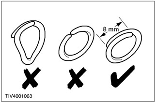
1. Use bent ring pliers to close the bent rings. Do not use any other tools. Curved rings need to be overlapped as shown.
Vehicles with side airbags
2. Install the side airbag module. See Section 501-20A / 501-20B for more information.
All cars
3.
WARNING: Make sure the anti-creak mat is properly positioned on the seat frame. Failure to heed this warning may make it difficult to deploy the airbag and cause injury. Anti-squeak carpeting is sold as a one-size-fits-all support material that must be cut to fit the replacement carpet.
NOTE: Install an anti-squeak mat to the seatback frame.
Install an anti-squeak mat.
4.
WARNING: Make sure the seat back foam is properly positioned around the side airbag module. If a new seatback foam pad is being installed on a 3-door vehicle, the foam padding must be cut to facilitate installation of the tilt arm mechanism.
Install the seat back foam pad.
3-door options
5.
NOTE: If installing a new seat back foam pad, the foam pad must be notched to facilitate installation of the tilt arm mechanism.
Using the tilt arm trim as a template, cut the seat back foam around the perimeter of the top inner edge of the trim.
All cars
6.
NOTE: If installing a new seat back foam pad, a hole must be drilled in the foam pad to facilitate wiring harness installation.
Install heater mat (in the presence of).
7. Insert the side tension rods into the seat cover if installing a new seat cover.
8. Attach the seat cover attachment strip to the back of the top of the seat frame.
- 1. Install the seat cover on the seat frame.
- 2. Attach the plastic fastening strip.
Vehicles with side airbags
9. Attach the plastic fastening strip to secure the side airbag deployment mechanism bushing.
10.
WARNING: Do not reuse the plastic mounting rivet. Always use a new rivet from the service kit. Failure to observe this warning may make it difficult to deploy the airbag and cause bodily injury.
Install the side airbag deployment mechanism bushing.
- Insert the colored plastic rivet into the plastic fastening strip that secures the side airbag module deployer bushing.
All cars
11. Install the bent seat cover mounting rings to the top edge of the spring frame assembly.
12. Roll the seat cover up and down on the seatback frame to the top spring frame assembly.
13. Attach the top ends of the side tension rods.
14. Roll out the seat cover along the back of the seat.
15. Attach the lower ends of the side tension rods.
16. Roll the seat cover up and down on the seatback.
3-door options
17. Establish an edging of the lever of blocking of a back of a seat.
18. Insert the outer lock lever cable into the lock lever housing.
19. Install the seat back lock lever housing
20. Install the seat back lock lever inner cable.
21. Install the seatback lock lever cables in the seatback base.
All cars
22. Install armrest (in the presence of).
23. Install the lumbar support adjustment mechanism (in the presence of).
24. Attach the plastic fastening strip to the base of the seatback.
25. Install the head restraint guide tubes.
26. Install the head restraint.
Visitor comments