OHC Engine Ignition Distributor
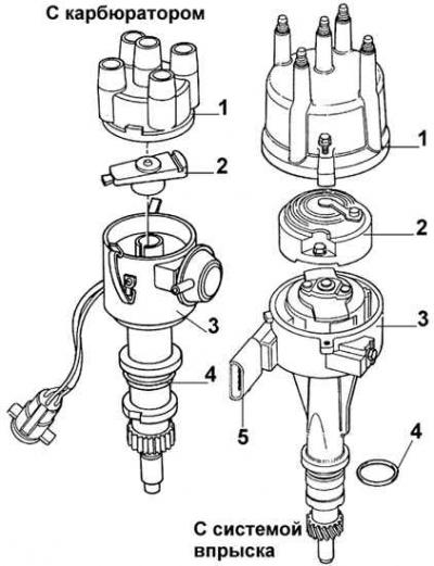
1 – cover, 2 – distributor rotor, 3 – ignition distributor, 4 – sealing ring, 5 – connector
DOHC Engine Ignition Distributor
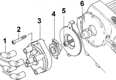
1 – high-voltage wire tips, 2 – cover fastening screw, 3 – cover, 4 – distributor rotor, 5 – bolt, 6 – distributor drive
DOHC Engine High Voltage Wires and Spark Plugs
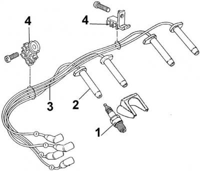
1 – spark plug, 2 – tip, 3 – high-voltage wires, 4 – high-voltage wire holders
Position of the distributor rotor before and after removal
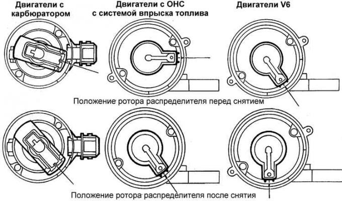
All engines except V6 2.4 and 2.9 dm³
Caution! The ignition distributor must not be removed without a serious reason, since the accuracy of the ignition timing achieved in production can hardly be restored.
1. Remove the negative cable from the battery.
2. Remove the distributor cap.
3. Using a wrench, turn the engine by the crankshaft pulley bolt until the piston of cylinder 1 is set to the ignition point, that is, when:
- the alignment marks are in the aligned position;
- the distributor rotor is aligned with the contact of the high-voltage wire of cylinder 1.
4. When the cylinder is in the ignition position, the rotor should align with the groove on the distributor housing.
5. Press the locking clamp on the multi-pin distributor connector and disconnect the connector.
6. Mark the alignment marks on the distributor and engine, then unscrew the distributor mounting bolt and clamping plate. On V6 engines, a special key must be used due to limited access. If a support bracket is installed, unscrew it.
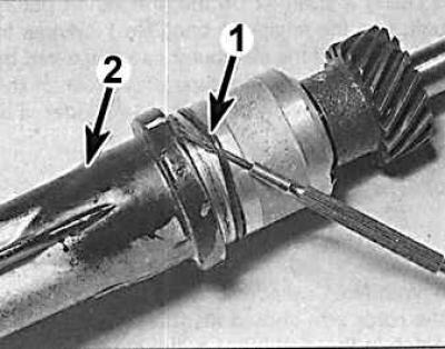
7. Remove the ignition distributor, marking the new position of the distributor rotor. The distributor rotor and O-ring (1) are supplied as spare parts for the distributor (2).
8. When installing the ignition distributor, set the rotor to the position it was in after removal, i.e. it should be turned 20° clockwise from the moment of ignition of cylinder 1.
9. Install the ignition distributor on the engine, while the distributor rotor should turn counterclockwise and set in the position it was in before removal, otherwise repeat the installation. The correct installation of the ignition distributor is determined by the alignment of the mark (1) on the rotor with the protrusion (2) on the distributor body. To accurately align the mark and the protrusion, it is necessary to turn the distributor body in one direction or the other.
10. Install the clamping bar and secure the distributor with the bolt.
11. Further installation is carried out in the reverse order of removal.
V6 engines 2.4 AND 2.9 dm³
Caution! The ignition distributor must not be removed without a serious reason, since the accuracy of the ignition timing angle can only be achieved using special equipment.
Rotor position before and after installation on a V6 2.4 and 2.9 dm³ engine
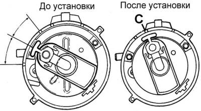
C – mark on the body
1. Remove the negative cable from the battery.
2. Remove the high-voltage wires from the spark plugs.
3. Remove the distributor cap and move it to the side along with the wires.
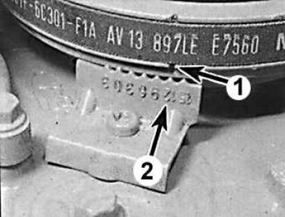
4. Turn the engine by the vibration damper mounting bolt to the piston installation point of cylinder 1 at the moment of ignition (12° before top dead center), aligning the mark on the crankshaft pulley (1) with the 12° division on the ignition timing scale (2).
5. If there is no mark on the crankshaft pulley, apply alignment marks in order to accurately install the distributor rotor later.
6. Mark the position of the distributor mounting plate relative to the cylinder block.
7. Disconnect the connector from the ignition distributor.
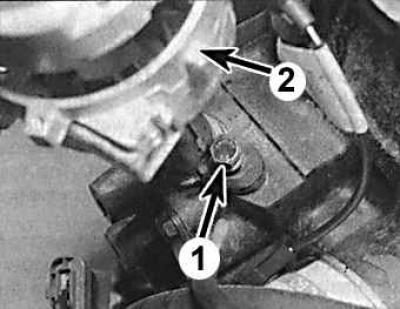
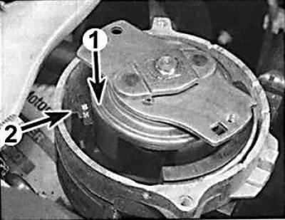
8. Unscrew the mounting bolt (1) and remove the ignition distributor (2).
9. Install the ignition distributor so that the installation marks are aligned.
10. After installing the distributor, rotate the distributor housing to align the rotor contact with mark C on the housing (see Fig. Rotor position before and after installation on a V6 2.4 and 2.9 dm³ engine) and secure the distributor in this position with a bolt.
11. Further installation is carried out in the reverse order of removal.
12. Warm up the engine and check the ignition timing.
The original can be found on this resource [fordbook]