Remove the Mecatronik II hydraulic unit as follows:
- Disconnect a wire from the negative plug of the storage battery;
- Remove the air filter, air flow meter and all related pipes and hoses, as described in the engine removal subsections;
- completely seal the locking connection of the expansion tank with adhesive tape, thereby preventing leakage of the brake fluid;
- remove the main brake cylinder together with the compensation tank, as described in the relevant section, temporarily shift the cylinder to the left side of the left suspension;
- remove the brake booster, for which unscrew the brake pedal mount and remove the booster with the shaft as a single unit;
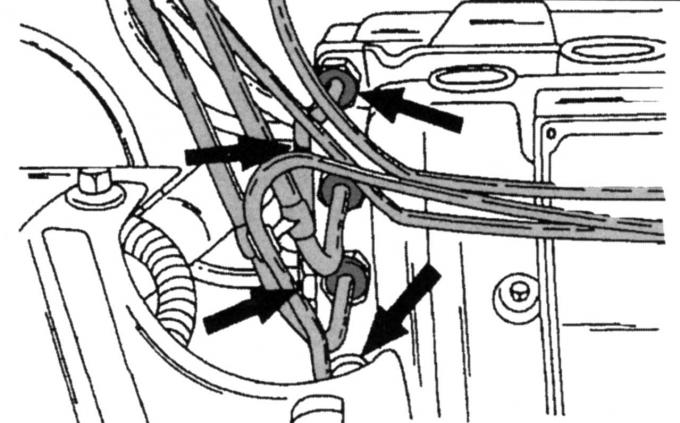
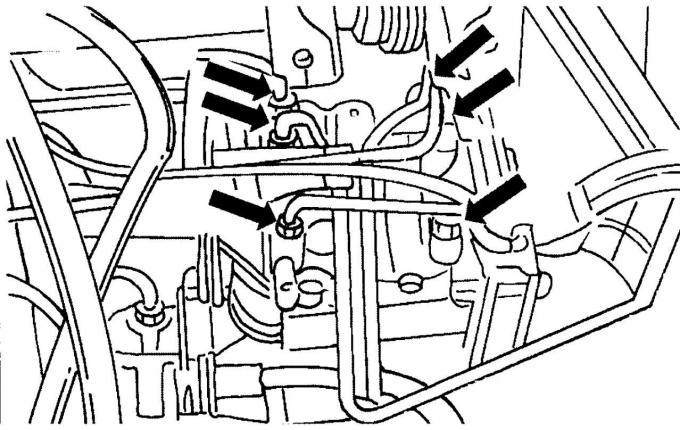
Pic. 269. Disconnection of tubes from the hydraulic unit
- disconnect all brake pipes from the hydraulic unit (pic. 269), close open connections and pipe ends in a suitable way (sticky tape), to avoid getting dirt and other foreign objects into them;
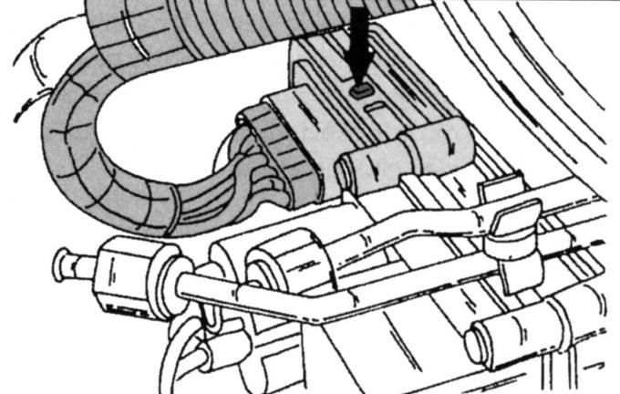
Pic. 270. Connector hydraulic control unit
- a multi-pin plug connector is connected to the hydraulic unit, press the safety lug on it and disconnect it (connector is connected at the location shown in fig. 270);
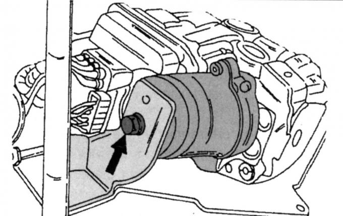
Pic. 271. Pump mounting from the back side
- unscrew the pump mounting bolts from the reverse side (pic. 271), slowly lift the hydraulic device from the left side and remove it from the right stop; make sure that none of the fastening parts fall, on this side there are loose inserts with pin bolts, in addition, a cap with a pin screw and an insulating ring are free;
- in diesel engines, remove the heat-insulating sheet.
Assemble the hydraulic unit as follows:
- install the cap with the pin screw and the insulating ring;
- insert the unit from the right side and then insert the inserts with pin screws into the suspension rubber, these inserts must be in place in the holder;
- lower the left end into the holder and tighten the screw shown in fig. 271 nuts with a torque of 20 Nm;
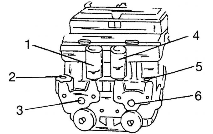
Pic. 272. Places of connection of brake pipes to the hydraulic unit
- carry out the rest of the work in reverse order (places of connection of brake tubes are shown in fig. 272);
- Connect in place 1 brake pipe leading to the right front brake;
- connection 2 leads to the front left brake circuit;
- connection 3 is a secondary output (for intermediate piston) master brake cylinder;
- connection 5 leads to the front right brake circuit;
- connection 6 is the output of the pressure piston of the main brake cylinder;
- after assembly, bleed the brake system as described in the relevant section;
- check the operation of the brake system and ABS.
Removal of the Mecatronik III hydraulic unit is carried out in the same order, except for the removal of the brake booster.
Further removal is carried out as follows:
Pic. 273. Disconnecting the brake pipes on the Mecatronik III hydraulic unit
- Disconnect brake pipes in the places shown on fig. 273;
- Disconnect the pipeline with a brake liquid from a fixing bracket;
- loosen the bolts on the left side of the hydraulic unit from the holder, and then unscrew it on the right side;
- remove the hydraulic unit together with the holder;
- if necessary, disconnect the mounting bracket from the hydraulic unit.
Install in the reverse order of removal. If the hydraulic unit has been turned away from the mounting bracket, tighten it with a torque of 14 Nm. Tighten the holder mounting bolts on the right and left to a torque of 25 Nm, brake pipes to a torque of 14 Nm, then bleed the brake system.
Visitor comments