Special tool
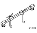 | Engine support beam 303-290A (21-140) |
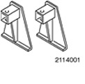 | Adapter for 303-290A (21-140) 303-290-01 (21-140-01) |
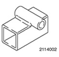 | Adapter for 303-290A (21-140) 303-290-02 (21-140-02) |
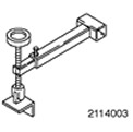 | Adapter for 303-290A (21-140) 303-290-03 (21-140-03) |
General equipment:
- Jack for gearbox
- Fixing clamps
| Name | Specification |
| Extreme pressure lubricant | SAM-1C9107-A |
1. Using an appropriate gearbox jack, install the gearbox in the drive axle assembly.
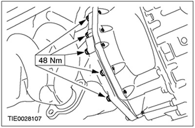
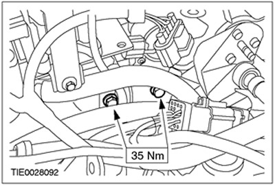
2. Establish the left bolts of fastening of a transmission in the block with the leading bridge.
3. Remove the gearbox jack. Remove fixing clamps.
4. Establish the right bolts of fastening of a transmission in the block with the leading bridge.
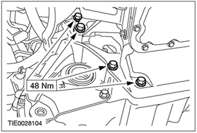
5. Fix a starter on a transmission in the block with a leading bridge.
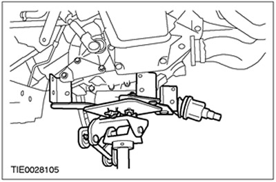
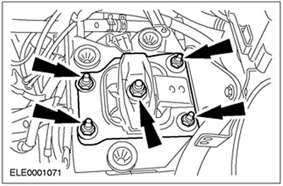
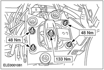
6. Install the rear engine mount bracket.
7. Connect the clutch slave cylinder feed line bracket to the rear engine mount bracket.
• Install the rear engine mount bracket bolts.
8. Lower the car.
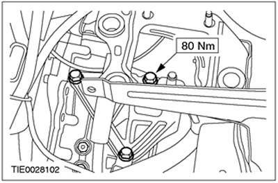
9. Tighten bolts of fastening of an arm of a back support of the engine.
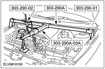
10. Using the special tools, lift the engine/transaxle assembly.

11.
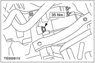
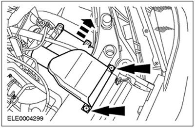
NOTE: Install a new rear engine mount center nut.
NOTE: Do not tighten rear engine mount nuts at this stage.
Install the rear engine mount.
12. Remove special tools.
13. Raise and support the vehicle. See Section 100-02 for more information.
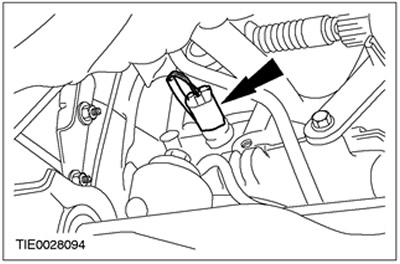
14. Connect the vehicle speed sensor connector (VSS).
15.
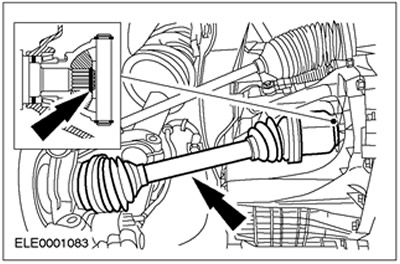
CAUTION: Support axle shaft. The inner hinge should not be tilted more than 18 degrees. External hinge - at an angle exceeding 45 degrees.
CAUTION: Be careful not to damage the axle shaft oil seal.
CAUTION: Make sure the snap ring is installed correctly.
NOTE: Install a new circlip.
Connect the left axle shaft to the gearbox in the block with the drive axle.
16.
CAUTION: Support axle shaft. The inner hinge should not be tilted more than 18 degrees. External hinge - at an angle exceeding 45 degrees.
CAUTION: Be careful not to damage the axle shaft oil seal.
NOTE: Install new axle shaft intermediate bearing cap and appropriate locknuts.
Connect the right axle shaft and the intermediate shaft to the gearbox in the block with the drive axle.
- Install the intermediate support cover.
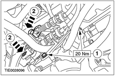
17. Connect the shift cables to the gearbox in the block with the drive axle.
- 1. Connect the support bracket to the transaxle assembly.
- 2. Connect the shift cable and gear select cable to the gear select levers.
18. Lubricate the exhaust system flex pins with a lubricant such as an anti-seize lubricant.
19.
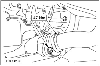
NOTE: Install a new exhaust flex gasket and new exhaust flex nuts.
Connect the flexible connector of the exhaust system to the exhaust pipe assembly with muffler.
20.
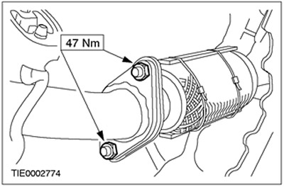
NOTE: Install a new catalytic converter gasket and new catalytic converter nuts.
Connect the catalytic converter to the exhaust manifold.
- Connect heated oxygen sensor (HO2S) to the catalytic converter.
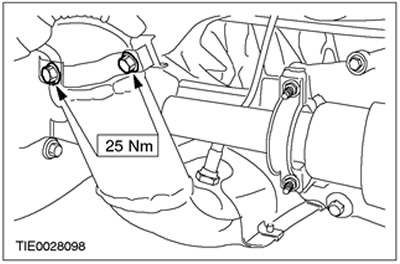
21. Install the catalytic converter bracket.
- Connect the catalytic converter monitoring oxygen sensor to the catalytic converter.
22.
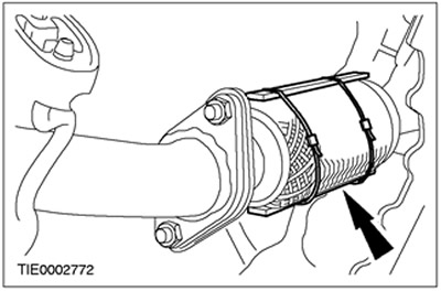
CAUTION: Do not excessively kink or twist the flexible connector of the exhaust system. Failure to follow this instruction may result in damage to the exhaust system flex.
Remove the exhaust flex support.
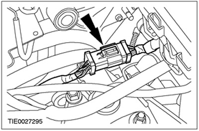
23. Connect the reversing light switch connector.
24. Install the subframe. See Section 502-00 for more information.
25. Lower the car.
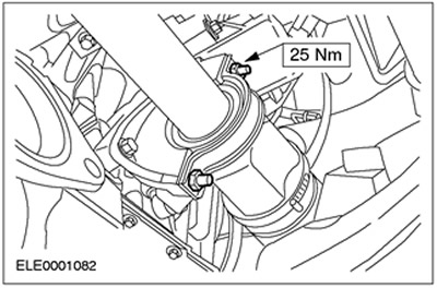
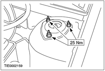
26. Tighten the nuts securing the upper support of the rack assembly with the spring (at both sides).
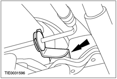
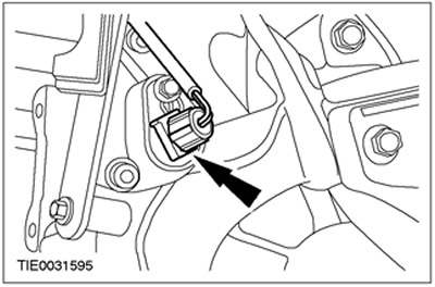
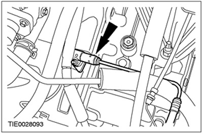
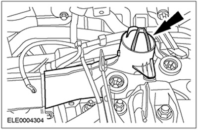
27. Connect the supply pipe of the clutch slave cylinder to the gearbox in the block with the drive axle. Install the clamp.
28. Connect the plug connector of the engine wiring harness to the gearbox in the block with the driving axle.
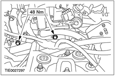
29. Install the starter mounting bolts.
- Connect the ground cable to the transaxle box.
30. Establish the top bolts of fastening of a transmission in the block with the leading bridge.
31. Tighten the rear engine mount nuts.
32.
NOTE: The resonator is inserted into the bracket.
Install the air cleaner intake resonator.
33. Install the inlet pipeline.
34. Connect the ground cable.
35. Install the air filter intake pipe. See Section 303-12 for more information.
36. Install the air filter. See Section 303-12 for more information.
37. Install the battery rack. See Section 414-01 for more information.
38.
NOTE: The shift lever must be in the 3rd and 4th shift channel.
Adjust shift cables. See Section 308-00 for more information.
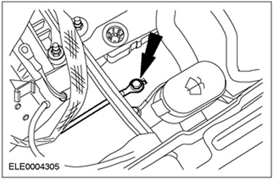
39. Remove air from the clutch system. See Section 308-00 for more information.
40. Check the transmission fluid level and add manual transmission fluid if necessary. For more information, refer to the chapter Draining Transmission Fluid from the Transaxle Transmission and Filling Transmission Fluid into the Transaxle Transmission in this section.
Visitor comments