General form
General information
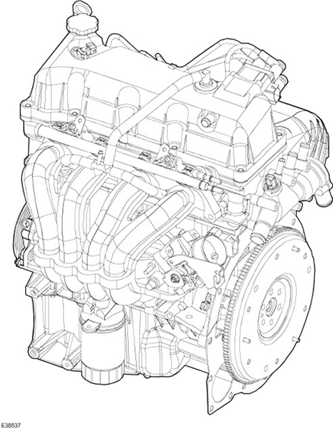
The Duratec 8V engine is an in-line, transversely mounted, four-cylinder engine with a single overhead camshaft and a cross-scavenged cylinder head (intake and exhaust channels are located on opposite sides).
Features of the Duratec 8V engine:
- Cast iron cylinder block with integral timing chain housing
- The crankshaft is supported by 5 bearings
- Cast aluminum cylinder head with integral timing chain housing
- Camshaft drive provided by timing chain with hydraulic tensioner
- The camshaft is supported by 5 bearings
- Two valves per cylinder
- Roller valve lifters
- Valve clearance adjustment via hydraulic tappets
- Double Layer Cylinder Head Gasket
- Aluminum oil sump with stiffeners
- Crankshaft driven oil pump
Engine identification
The serial number of the engine is indicated on the flywheel housing on the exhaust side.
In addition, in the same place, the chassis number is indicated in short form (VIN) and warning sign.
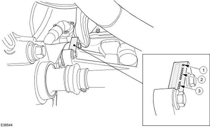
| Pos. | Spare Part No | Name |
| 1 | - | warning sign |
| 2 | - | VIN |
| 3 | - | Engine code |
Engine types
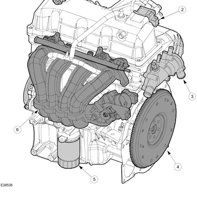
| Pos. | Spare Part No | Name |
| 1 | - | Camshaft position sensor (CMP) |
| 2 | - | Electronic ignition module (EI) |
| 3 | - | thermostat housing |
| 4 | - | Flywheel |
| 5 | - | Oil filter |
| 6 | - | Air intake module |
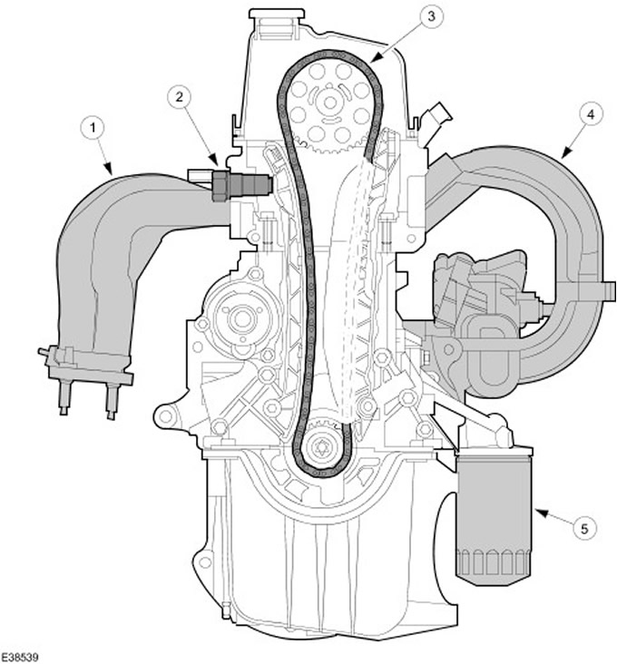
| Pos. | Spare Part No | Name |
| 1 | - | An exhaust manifold |
| 2 | - | Hydraulic chain tensioner |
| 3 | - | Timing chain |
| 4 | - | Air intake module |
| 5 | - | Oil filter |
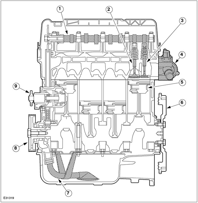
| Pos. | Spare Part No | Name |
| 1 | - | Camshaft |
| 2 | - | Inlet valve |
| 3 | - | Exhaust valve |
| 4 | - | thermostat housing |
| 5 | - | Pistons |
| 6 | - | Flywheel |
| 7 | - | Receiving oil pipeline |
| 8 | - | Belt pulley |
| 9 | - | coolant pump |
Cylinder head cover
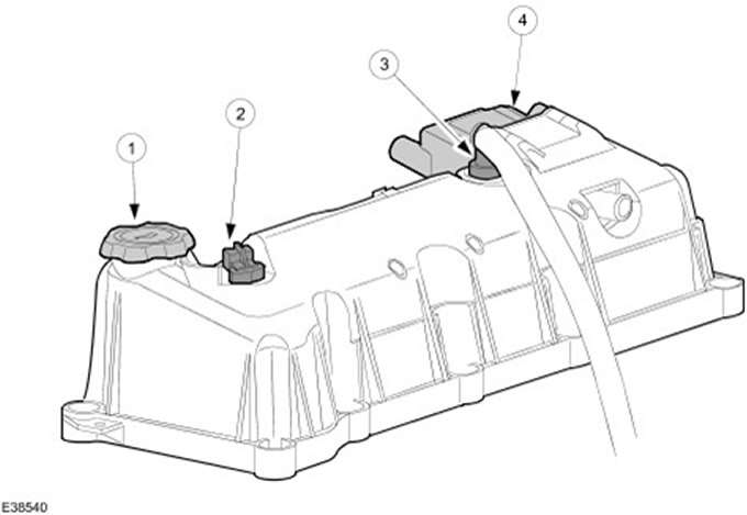
| Pos. | Spare Part No | Name |
| 1 | - | Oil filler cap |
| 2 | - | CMP sensor |
| 3 | - | Positive crankcase ventilation valve (PCV) |
| 4 | - | EI module |
| 5 | - | Fuel vapor control solenoid valve (EVAP) |
The cylinder head cover is attached to the cylinder head with ten bolts.
The cylinder head cover gasket has a T-section and is fixed in the groove of the cylinder head cover.
The CMP sensor is mounted on the cylinder head cover and is used to determine the position of cylinder #1.
The EI module is bolted to the wall of the cylinder head cover with four bolts.
The EVAP solenoid valve is mounted on an optional bracket.
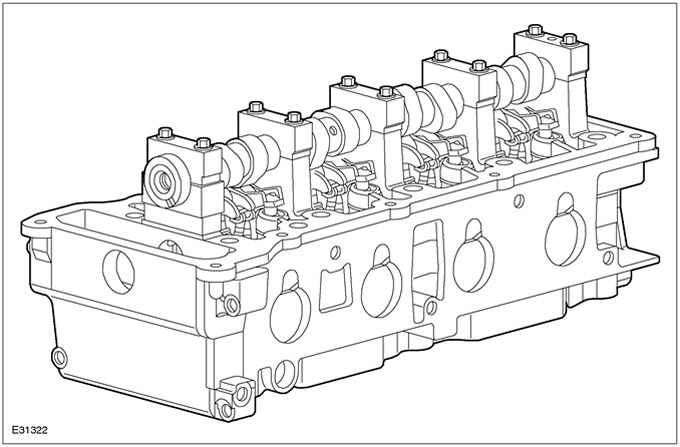
The cylinder head is made of aluminum alloy and features two valves per cylinder.
This is the so-called cross-flow cylinder head, i.e. intake and exhaust valves are located on opposite sides.
The angles of the intake and exhaust valves are asymmetrical. The intake valve angle is 10°and the exhaust valve angle is 6°.
The spark plugs are located on the exhaust side.
Valve guides and valve seats are made of sintered metal.
The timing chain housing is an integral part of the cylinder head and cylinder block.
Valve mechanism
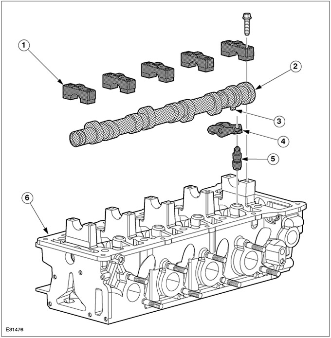
| Pos. | Spare Part No | Name |
| 1 | - | Camshaft bearing cap |
| 2 | - | Camshaft |
| 3 | - | base cam |
| 4 | - | Roller tappet |
| 5 | - | hydraulic pusher |
| 6 | - | cylinder head |
The camshaft is held in position by five bearing caps and rests directly on the cylinder head - no bearing shells.
The camshaft has an additional base cam to identify cylinder #1.
The camshaft drives the valve lifters.
Due to the fact that the valve lifters are supported by rollers, friction losses in the valve mechanism are reduced.
As a result of using hydraulic tappets, no valve clearance adjustment is required.
Inlet and outlet valves
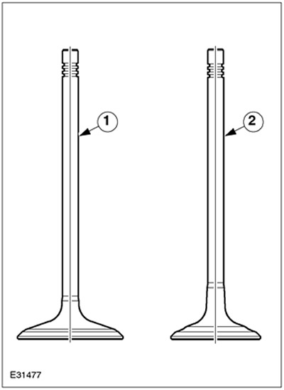
| Pos. | Spare Part No | Name |
| 1 | - | Inlet valve |
| 2 | - | Exhaust valve |
The inlet valve is completely made of one material. The exhaust valve is a bimetal valve.
Cylinder head gasket
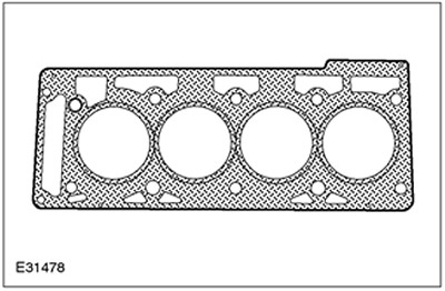
The cylinder head gasket is a two-layer metal gasket.
Cylinder block
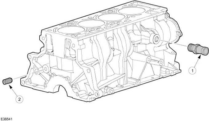
| Pos. | Spare Part No | Name |
| 1 | - | Connection for forced crankcase ventilation |
| 2 | - | Oil gallery plug |
CAUTION: The oil gallery plug must not be removed.
The cylinder head is made of cast iron.
The cylinder block does not have any special cylinder liners.
The working surfaces of the cylinders are formed directly in the cylinder block.
The positive crankcase ventilation connection is located on the rear side of the cylinder block.
Crankshaft and bearing caps
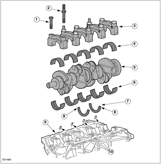
| Pos. | Spare Part No | Name |
| 1 | - | bolts (6 pcs.) |
| 2 | - | Bolts combined with studs (4 things.) |
| 3 | - | Main bearing caps |
| 4 | - | Main bearing shells (without lubrication oil groove) |
| 5 | - | Crankshaft |
| 6 | - | Main bearing shells (with oil lubrication groove) |
| 7 | - | Thrust washers |
| 8 | - | beveled edge |
| 9 | - | Cylinder block |
| 10 | - | Oil nozzles |
The crankshaft is supported by five bearings and has four cheeks.
The main bearing caps are numbered and marked with arrows to indicate installation position and orientation. After installing the covers, the arrows must point in the direction of the timing chain.
The main bearing shells that are nested in the main bearing caps do not have an oil groove.
The main bearing shells, which are nested in the cylinder block, have an oil groove.
Four of the main bearing cap bolts after the heads are continued with studs, which are used to secure the oil slinger plate and the oil pump intake pipe.
The axial clearance of the crankshaft is limited by two thrust washers.
Connecting rod
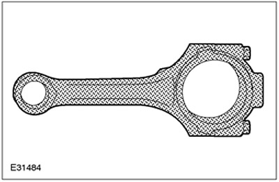
The connecting rods are made from forged steel. Connecting rods are divided into three different weight classes.
Pistons and piston rings
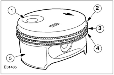
| Pos. | Spare Part No | Name |
| 1 | - | notch in the piston |
| 2 | - | Top compression ring |
| 3 | - | Lower compression ring |
| 4 | - | Oil scraper ring |
| 5 | - | Coating |
Lightweight pistons are made of aluminium. The piston skirt has a special coating to increase piston life. Pistons are available in only one diameter. The top compression ring has a rectangular section and is made of steel. The lower compression ring has an L-section and is made of cast iron. The oil scraper ring consists of three parts and has a chrome plating.
Crankshaft rear oil seal holder
| Pos. | Spare Part No | Name |
| 1 | - | sealant |
| 2 | - | Oil seal holder |
| 3 | - | Bolt |
| 4 | - | Mounting sleeve |
The mounting sleeve is made of plastic. The oil seal is built into the oil seal holder. The oil seal is made of PTFE (PTFE). The oil seal holder is centered on two guide pins and then bolted to the cylinder block with four bolts.
Oil baffle plate and oil intake pipe
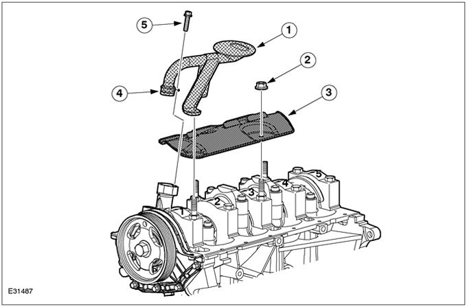
| Pos. | Spare Part No | Name |
| 1 | - | Receiving oil pipeline |
| 2 | - | screw |
| 3 | - | Oil deflector plate |
| 4 | - | O-ring of circular cross-section |
| 5 | - | Bolt |
The oil slinger prevents excessive foaming of the engine oil.
The oil baffle plate and the oil intake pipe are fastened by means of studs, which are a continuation of the bolts for fastening the bearing caps.
The oil intake pipe is sealed against the oil pump by means of an O-ring.
oil sump
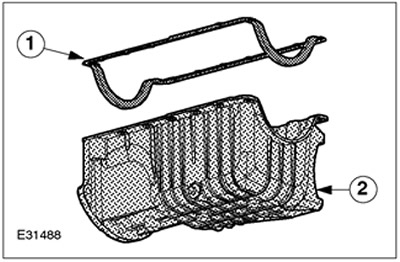
| Pos. | Spare Part No | Name |
| 1 | - | Oil pan gasket |
| 2 | - | oil sump |
The oil sump is made of aluminum alloy and has stiffeners. An A/C compressor bracket is built into the oil sump. The oil pan gasket consists of an aluminum base coated with a rubber coating.
Flywheel
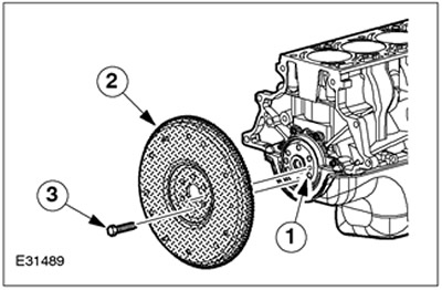
| Pos. | Spare Part No | Name |
| 1 | - | Centering sleeve |
| 2 | - | Flywheel |
| 3 | - | bolts |
The flywheel is made of cast iron. The flywheel is attached to the crankshaft with six bolts and centered with a special centering sleeve.
Camshaft drive
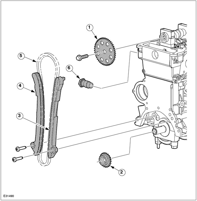
| Pos. | Spare Part No | Name |
| 1 | - | Camshaft sprocket |
| 2 | - | crankshaft sprocket |
| 3 | - | Front chain guide |
| 4 | - | Rear chain guide |
| 5 | - | Timing chain |
| 6 | - | Hydraulic chain tensioner |
Camshaft sprocket and crankshaft sprocket
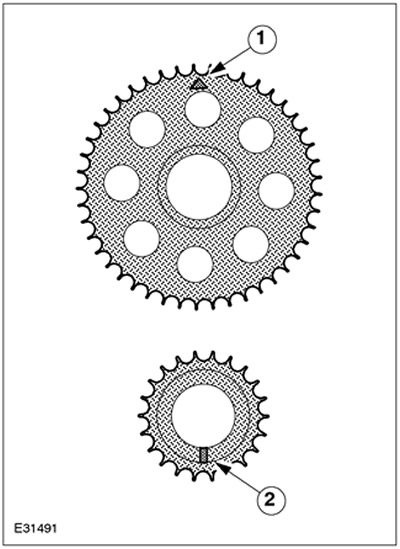
| Pos. | Spare Part No | Name |
| 1 | - | Mounting mark |
| 2 | - | Segmented key |
The camshaft sprocket is made of steel and has 38 teeth. The installation mark is stamped on the front. The crankshaft sprocket is made of sintered steel and has 19 teeth. The installation position of both sprockets is determined by the segment key.
Timing chain
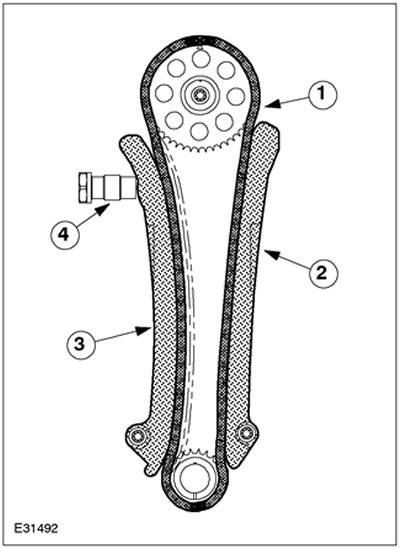
| Pos. | Spare Part No | Name |
| 1 | - | Timing chain |
| 2 | - | Chain guide (intake side) |
| 3 | - | Chain guide (release side) |
| 4 | - | Hydraulic chain tensioner |
The timing chain is a bush type chain with 114 links. Chain guides are made of plastic. Both chain guides are bolted on. The chain guide on the intake side also passes through a recess in the cylinder head. The chain guide on the exhaust side can be slid and moved by means of a hydraulic chain tensioner.
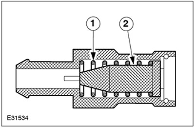
Hydraulic chain tensioner
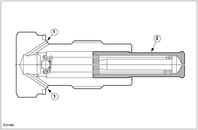
| Pos. | Spare Part No | Name |
| 1 | - | Oil supply |
| 2 | - | Pistons |
The hydraulic chain tensioner moves under the influence of engine oil pressure. The piston rests against the chain guide (release side) and ensures the creation of a certain contact pressure on the timing chain.
Oil circuit
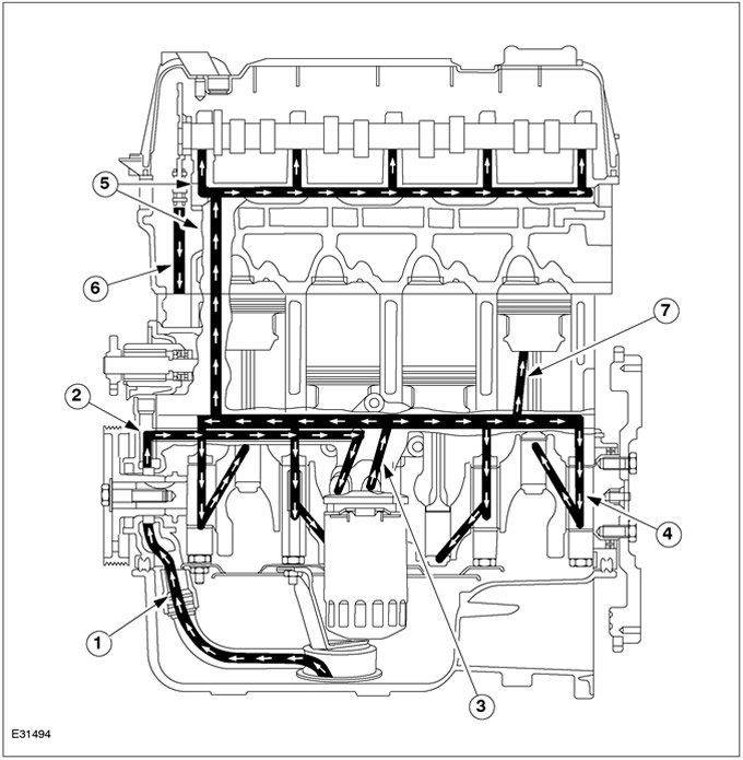
| Pos. | Spare Part No | Name |
| 1 | - | From oil intake pipe to oil pump |
| 2 | - | From oil pump to oil filter |
| 3 | - | From oil filter to main oil gallery |
| 4 | - | From main oil gallery to main bearings |
| 5 | - | Oil gallery leading to the cylinder head and to the camshaft |
| 6 | - | Return oil channel |
| 7 | - | oil splatter |
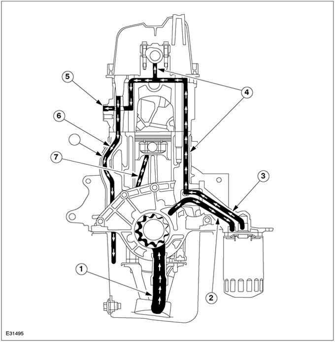
| Pos. | Spare Part No | Name |
| 1 | - | From oil intake pipe to oil pump |
| 2 | - | From oil pump to oil filter |
| 3 | - | From oil filter to main oil gallery |
| 4 | - | Oil gallery leading to the cylinder head and to the camshaft |
| 5 | - | Oil supply to the hydraulic chain tensioner |
| 6 | - | Return oil channel |
| 7 | - | oil splatter |
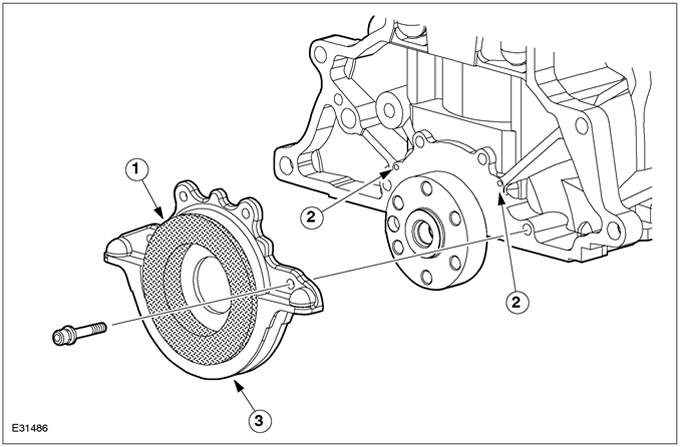
Oil pump
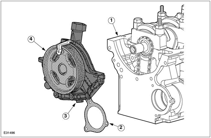
| Pos. | Spare Part No | Name |
| 1 | - | Cylinder block |
| 2 | - | Gasket for oil pump and coolant pump |
| 3 | - | Oil pump |
| 4 | - | Oil pump pulley |
The oil pump is a G-rotary type pump which is directly driven by the engine. Crankshaft oil seal (PTFE) located in the oil pump housing. The oil pump housing gasket is a rubberized metal gasket.
Receiving oil pipeline
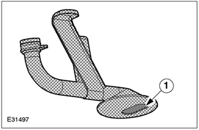
| Pos. | Spare Part No | Name |
| 1 | - | Mesh oil filter |
Engine oil is pumped from the oil sump to the oil pump through the oil intake pipe. The oil intake pipe is made of steel. The strainer is located on the underside of the oil intake pipe. This strainer prevents the oil pump from being damaged by particles present in the oil.
Oil filter and oil filter adapter
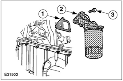
| Pos. | Spare Part No | Name |
| 1 | - | Pad |
| 2 | - | Oil filter and oil filter adapter |
| 3 | - | Bolt |
NOTE: Once the oil filter adapter has been disassembled, the gasket cannot be reused.
The oil filter adapter is made of aluminum alloy. The metal gasket of the oil filter adapter is rubberized.
General view of PCV
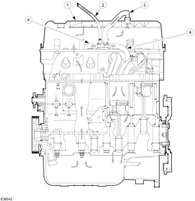
| Pos. | Spare Part No | Name |
| 1 | - | Cylinder head cover with integrated oil separator |
| 2 | - | From the EVAP solenoid valve |
| 3 | - | From PCV |
| 4 | - | To intake manifold |
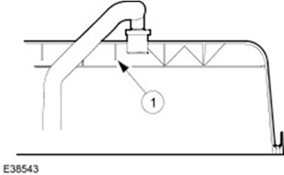
PCV valve
| Pos. | Spare Part No | Name |
| 1 | - | Spring |
| 2 | - | Pistons |
The PCV valve is located on the top side of the cylinder head cover. Gases from the crankcase are sucked off by the PCV valve into the intake manifold. The PCV valve is opened by the vacuum present in the intake manifold. The amount of gases present in the crankcase depends on the engine speed. The suctioned quantity is set by the spring and the shape of the piston.
Reflective plate
| Pos. | Spare Part No | Name |
| 1 | - | reflective plate |
The reflective plate is integrated into the cylinder head cover. This prevents the oil from being sucked in and burned during the combustion process. The oil droplets condense on the baffle plate and then return to the oil circuit.
Visitor comments