NOTE: Use a digital multimeter to make all electrical measurements.
PINPOINT TEST A: NO SVC DISPLAYED ON THE AUDIO UNIT
|
STATES |
DETAILS/RESULTS/ACTIONS |
|
A1: CHECK ANTENNA CONNECTION |
|
|
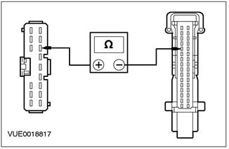
CAUTION: When making electrical measurements, the antenna cable connectors must not be short-circuited with DMM probes as this will damage the antenna cable and require installation of the antenna cable. |
|
|
1 MAKE SURE all antenna cable connectors are mated. |
|
|
• Are the antenna cable connectors mated? |
|
|
→ Yes |
|
|
Go to A2 |
|
|
→ No |
|
|
MATCH the antenna connectors. Check the correct operation of the system. |
|
|
A2: CHECK ANTENNA CABLE FOR OPEN |
|
|
1 Disconnect Antenna Connectors.. |
|
|
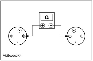
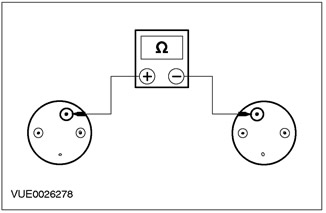
2 Measure the resistance between the top end of the antenna cable and the bottom end of the antenna cable. |
|
• Is the resistance less than 5 ohms? |
|
|
→ Yes |
|
|
INSTALL a new antenna base. Check the correct operation of the system. If the problem persists, INSTALL a new telematics control unit. Check the correct operation of the system. |
|
|
→ No |
|
|
INSTALL a new antenna cable. CHECK the system is working properly. |
|
PINPOINT TEST B: AUDIO UNIT DISPLAYS GPS
|
STATES |
DETAILS/RESULTS/ACTIONS |
|
B1: CHECK ANTENNA CONNECTION |
|
|
CAUTION: When making electrical measurements, the antenna cable connectors must not be short-circuited with DMM probes as this will damage the antenna cable and require installation of the antenna cable. |
|
|
1 MAKE SURE all antenna cable connectors are mated. |
|
|
• Are the antenna cable connectors mated? |
|
|
→ Yes |
|
|
Navigate to B2 |
|
|
→ No |
|
|
MATCH the antenna connectors. CHECK the system is working properly. |
|
|
B2: CHECK ANTENNA CABLE FOR OPEN |
|
|
1 Disconnect the antenna cable connectors. |
|
|
2 Measure the resistance between the top end of the antenna cable and the bottom end of the antenna cable. |
|
• Is the resistance less than 5 ohms? |
|
|
→ Yes |
|
|
Go to B3 |
|
|
→ No |
|
|
INSTALL a new antenna cable. CHECK the system is working properly. |
|
|
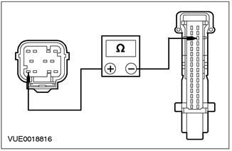
B3: CHECK THE VOLTAGE AT THE ANTENNA BASE |
|
|
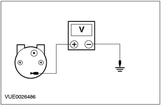
1 Connect the lower antenna connector. |
|
|
2 Measure the voltage between the top end of the antenna cable and "weight". |
|
• Is the voltage over 10 V? |
|
|
→ Yes |
|
|
INSTALL a new antenna base. CHECK the system is working properly. |
|
|
→ No |
|
|
INSTALL a new antenna cable. CHECK the system is working properly. |
|
PINPOINT TEST C: AUDIO UNIT DISPLAYS SPEEDSIG
|
STATES |
DETAILS/RESULTS/ACTIONS |
|
C1: INSPECT CIRCUIT 15-MD15 (GREEN/BLACK) FOR VOLTAGE |
|
|
1 Drive the ON position. |
|
|
2 Disconnect the telematics control unit - C521. |
|
|
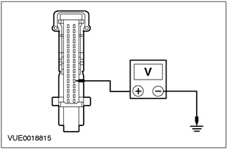
3 Measure the voltage between pin 28 C521 of the telematics control unit, circuit 15-MD15 (green/black), from the wiring side, and "weight". |
|
• Is the voltage over 10 V? |
|
|
→ Yes |
|
|
Go to C2 |
|
|
→ No |
|
|
REPAIR the electrical circuit. PERFORM the Element Tests described in this section. |
|
|
C2: INSPECT 8-MD24B CIRCUIT (WHITE/GREEN) ON OPEN |
|
|
1 Enter the OFF position. |
|
|
2 Detach Information and Message Center - C63. |
|
|
3 Measure the resistance between pin 5 C521 of the telematics control unit, circuit 8-MD24B (white/green), on the wiring side, and pin 9 C63 of the information and message center, electrical circuit 8-MD24B (white/green), from the side of the electrical wiring. |
|
• Is the resistance less than 5 ohms? |
|
|
→ Yes |
|
|
See Section 310-03 for more information. |
|
|
→ No |
|
|
REPAIR the electrical circuit. PERFORM the Element Tests described in this section. |
|
PINPOINT TEST D: AIRBAG DISPLAYED ON THE AUDIO UNIT
|
STATES |
DETAILS/RESULTS/ACTIONS |
|
D1: INSPECT CIRCUIT 15-MD15 (GREEN/BLACK) FOR VOLTAGE |
|
|
1 Drive the ON position. |
|
|
2 Disconnect the telematics control unit - C521. |
|

|
3 Measure the voltage between pin 28 C521 of the telematics control unit, circuit 15-MD15 (green/black), from the wiring side, and "weight". |
|
• Is the voltage over 10 V? |
|
|
→ Yes |
|
|
Go to D2 |
|
|
→ No |
|
|
Repair the electrical circuit. PERFORM the Element Tests described in this section. |
|
|
D2: INSPECT ELECTRICAL CIRCUIT 91S-AJ14B (BLACK/GREEN) ON OPEN |
|
|
1 Enter the OFF position. |
|
|
2 Disconnect the Airbag Diagnostic Monitor - C424. |
|
WARNING: Before performing any work on the secondary restraint system and adjacent components, the backup battery must be disconnected. Failure to follow this instruction may cause the air bag to deploy unexpectedly and result in personal injury. See Section 501-20A / 501-20B for more information. 3 Measure the resistance between pin 19 C521 of the telematics control unit, circuit 91S-AJ14B (black/green), wiring side, and pin 1 C424 of air bag diagnostic monitor, circuit 91S-AJ14B (black/green), from the side of the electrical wiring. |
|
|
• Is the resistance less than 5 ohms? |
|
|
→ Yes |
|
|
See Section 501-20A / 501-20B for more information. |
|
|
→ No |
|
|
Repair the electrical circuit. PERFORM the Element Tests described in this section. |
|
Item checks
Test call
NOTE: This check is available only if there are no faults or all faults have been corrected. This is indicated by the message SYS OK on the display of the audio unit when entering the Self-diagnosis Mode.
NOTE: This check must be performed when the vehicle is outside the workshop and there are no large buildings/structures or metal objects in the immediate vicinity, allowing the GPS antenna to receive signals from more than three GPS satellites.
NOTE: To exit the Self Test Mode manually, press the MENU button.
1. Enter the Self-diagnostic mode.
2. Press the SEEK button on the audio unit.
3. While the connection is being established, TESTCALL and CALLING will appear on the audio unit display.
4. During the connection, the audio unit's display alternates between TESTCALL and the current signal strength.
5. When the connection to the Ford telematics call center is established, the Ford telematics operator announces that you have successfully connected to the Ford telematics call center.
6. After announcing the operator of the Ford telematics system, the connection is terminated and automatic exit from the Self-diagnostic mode occurs. SRV END appears on the audio unit display along with the connection time.
Visitor comments