|
STATES |
DETAILS/RESULTS/ACTIONS |
|
A1: CHECK FOR CELL PHONE SYMBOL ON AUDIO UNIT |
|
|
1 Check the compatibility of the audio block. |
|
|
• Does the audio unit have a telephone symbol after the model number? |
|
|
→ Yes |
|
|
Go to A2 |
|
|
→ No |
|
|
INSTALL a new audio unit with a telephone symbol. CHECK the system is working properly. |
|
|
A2: CHECK THE PHONE SYMBOL ON AUDIO UNIT DISPLAY |
|
|
1 Drive the ON position. |
|
|
• INSTALL the cell phone on the handset bracket. When the unit is turned on, does the TELEPHONE SYMBOL appear on the audio unit display? |
|
|
→ Yes |
|
|
Go to A3 |
|
|
→ No |
|
|
Go to B3 Go to PINPOINT TEST B |
|
|
A3: INSPECT WIRING HARNESS 91S-MD37 FROM AUDIO UNIT TO PORTABLE SUPPORT MODULE |
|
|
1 Enter the OFF position. |
|
|
2 Disconnect the Handheld Support Module - C463. |
|
|
3 Disconnect the Audio Unit - C447. |
|
|
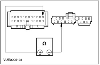
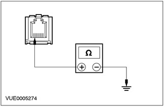
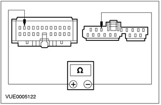
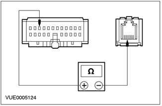
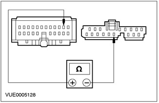
4 Using a digital multimeter, measure the resistance between pin 4 C447 of the audio unit, circuit 91S - MD37 (black/red), on the wiring side, and pin 11 C463 of the portable operation support module, electrical circuit 91S - MD37 (black/red), from the side of the electrical wiring. |
|
• Is the resistance less than 5 ohms? |
|
|
→ Yes |
|
|
Go to A4 |
|
|
→ No |
|
|
Repair the electrical circuit. CHECK the system is working properly. |
|
|
A4: CHECK THE VOLTAGE IN THE PORTABLE SUPPORT AREA |
|
|
1 Drive the ON position. |
|
|
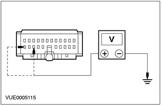
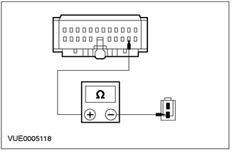
2 Using a DMM, measure the voltage between pin 10 C463 of the handheld support module, circuit 29-MC9 (orange/black), on the wiring harness side, and pin 8 C463 of the handheld support module, circuit 75-MC9 (yellow/green) from the side of the wiring harness and "weight". |
|
• Is the voltage more than 10 V in all cases? |
|
|
→ Yes |
|
|
Go to A5 |
|
|
→ No |
|
|
REPAIR Circuit 29-MC9 (orange/black) or electrical circuit 75-MC9 (yellow/green). CHECK the system is working properly. |
|
|
A5: CHECK GROUND CIRCUIT 91-MC9 (BLACK/GREEN) |
|
|
1 Enter the OFF position. |
|
|
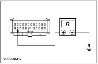
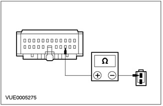
2 Using a digital multimeter, measure the resistance between C463 pin 9 of the handheld support module, circuit 91 - MC9 (black/green), from the wiring side, and "weight". |
|
• Is the resistance less than 5 ohms? |
|
|
→ Yes |
|
|
Go to A6 |
|
|
→ No |
|
|
Repair the electrical circuit. CHECK the system is working properly. |
|
|
A6: CHECK THE AUDIO UNIT IS FUNCTIONING PROPERLY |
|
|
1 Substitute with a known-good compatible audio unit. |
|
|
2 Drive the ON position. |
|
|
3 Check that the audio unit is working properly. |
|
|
• Does the message PHONE appear on the audio unit display when a cellular phone is placed on the handset bracket? |
|
|
→ Yes |
|
|
INSTALL a new audio unit. CHECK the system is working properly. |
|
|
→ No |
|
|
INSTALL the new portable support module. CHECK the system is working properly. |
|
PINPOINT TEST B: CELL PHONE BATTERY NOT CHARGING
|
STATES |
DETAILS/RESULTS/ACTIONS |
|
B1: CHECK CELL PHONE DISPLAY WHEN USED OUTSIDE OF VEHICLE |
|
|
1 Activate the cell phone outside the car. |
|
|
• Does the cell phone display indicate low battery? |
|
|
→ Yes |
|
|
Go to B2 Go to PINPOINT TEST B |
|
|
→ No |
|
|
CHECK your cell phone battery. REFER to the instruction manual of the cell phone. |
|
|
B2: CHECK BATTERY SYMBOL ON CELL PHONE |
|
|
1 Drive the ON position. |
|
|
• INSTALL the cell phone on the handset bracket. Is the battery symbol flashing? |
|
|
→ Yes |
|
|
The battery is charging correctly. WAIT for the battery to charge. CHECK the system is working properly. |
|
|
→ No |
|
|
Go to B3 Go to PINPOINT TEST B |
|
|
B3: CHECK THE VOLTAGE IN THE PORTABLE SUPPORT AREA |
|
|
1 Disconnect the Handheld Support Module - C463. |
|

|
2 Using a DMM, measure the voltage between pin 10 C463 of the handheld support module, circuit 29-MC9 (orange/black), on the wiring harness side, and pin 8 C463 of the handheld support module, circuit 75-MC9 (yellow/green) from the side of the wiring harness and "weight". |
|
• Is the voltage more than 10 V in all cases? |
|
|
→ Yes |
|
|
Go to B4 Go to PINPOINT TEST B |
|
|
→ No |
|
|
REPAIR Circuit 29-MC9 (orange/black) or electrical circuit 75-MC9 (yellow/green). CHECK the system is working properly. |
|
|
B4: CHECK 8-MC17 TUBE BRACKET VOLTAGE |
|
|
1 Disconnect the Tube Bracket - C471. |
|
|
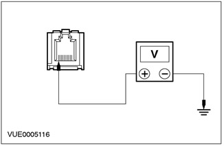
2 Using a digital multimeter, measure the voltage between pin 10 C471 of tube bracket, circuit 8 - MC17 (white/red), from the wiring side, and "weight". |
|
• Is the voltage over 10 V? |
|
|
→ Yes |
|
|
Go to B5 Go to PINPOINT TEST B |
|
|
→ No |
|
|
NOTE: If the connector is damaged, install a new wiring harness. REPAIR the electrical circuit. CHECK the system is working properly. |
|
|
B5: CHECK GROUND CIRCUIT 91-MC9 (BLACK/GREEN) |
|

|
1 Using a digital multimeter, measure the resistance between C463 pin 9 of the handheld support module, circuit 91 - MC9 (black/green), from the wiring side, and "weight". |
|
• Is the resistance less than 5 ohms? |
|
|
→ Yes |
|
|
Go to B6 Go to PINPOINT TEST B |
|
|
→ No |
|
|
REPAIR the electrical circuit. CHECK the system is working properly. |
|
|
B6: CHECK GROUND CIRCUIT 91-MC10 (BLACK/RED) |
|
|
1 Using a digital multimeter, measure the resistance between pin 9 C471 of tube bracket, circuit 91 - MC10 (black/red), from the wiring side, and "weight". |
|
• Is the resistance less than 5 ohms? |
|
|
→ Yes |
|
|
INSTALL the new portable support module. CHECK the system is working properly. |
|
|
→ No |
|
|
Repair the electrical circuit. CHECK the system is working properly. |
|
PINPOINT TEST C: CELL PHONE NOT IN SERVICE DUE TO LOW SIGNAL
|
STATES |
DETAILS/RESULTS/ACTIONS |
|
C1: CHECK CELL PHONE SIGNAL WHEN OUTSIDE VEHICLE |
|
|
NOTE: Make sure you have selected the correct cell phone service network before doing any checks. |
|
|
1 Use your cell phone while outside the vehicle. |
|
|
• Does the cell phone provide a good signal outside the car? |
|
|
→ Yes |
|
|
Go to C2 Go to PINPOINT TEST C |
|
|
→ No |
|
|
TEST the system in an area known to have good signal strength. |
|
|
C2: CHECK ANTENNA CONNECTION AT HANDLING BRACKET AREA |
|
|
1 Check the antenna cable connection. |
|
|
• Is the antenna connected to the handset bracket? |
|
|
→ Yes |
|
|
Go to C3 Go to PINPOINT TEST C |
|
|
→ No |
|
|
REPAIR the antenna connection. CHECK the system is working properly. |
|
|
C3: CHECK ANTENNA INSTALLATION |
|
|
1 Examine the antenna. |
|
|
• The antenna is correctly installed on the windshield. For more information refer to Antenna - Cell Phone available in this section.. |
|
|
→ Yes |
|
|
Go to C4 Go to PINPOINT TEST C |
|
|
→ No |
|
|
INSTALL the new antenna correctly. For more information refer to Antenna - Cell Phone available in this section. CHECK the system is working properly. |
|
|
C4: CHECK ANTENNA CABLE FOR SHORT CIRCUIT |
|
|
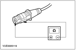
1 Using a digital multimeter, measure the resistance between the center conductor of the antenna and "weight" (screen) antennas. |
|
• Is the resistance between 9,000 and 10,000 ohms? |
|
|
→ Yes |
|
|
Go to C5 Go to PINPOINT TEST C |
|
|
→ No |
|
|
INSTALL a new antenna. For more information refer to Antenna - Cell Phone available in this section. CHECK the system is working properly. |
|
|
C5: CHECK ANTENNA TO HANDLING BRACKET CONNECTION |
|
|
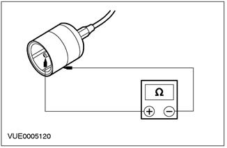
1 Using a digital multimeter, measure the resistance between the center conductor of the antenna and "weight" (screen) antennas. |
|
• Is the resistance between 9,000 and 10,000 ohms? |
|
|
→ Yes |
|
|
Go to C6 Go to PINPOINT TEST C |
|
|
→ No |
|
|
INSTALL a new antenna. For more information refer to Antenna - Cell Phone available in this section. CHECK the system is working properly. |
|
|
C6: CHECK CONNECTOR CONNECTING HANDSET BRACKET TO CELL PHONE |
|
|
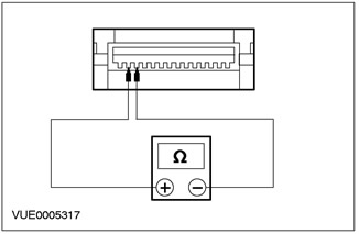
1 Using a digital multimeter, measure the resistance between C1026 tube bracket pin 2, wiring side, and C1026 tube bracket pin 3, wiring side. |
|
• Is the resistance between 9,000 and 10,000 ohms? |
|
|
→ Yes |
|
|
CHECK connection between cell phone and handset bracket. CHECK the system is working properly. |
|
|
→ No |
|
|
INSTALL a new tube bracket. For more information, refer to the Tube Bracket available in this section. CHECK the system is working properly. |
|
PINPOINT TEST D: MICROPHONE MODE "SPEAKER" CELL PHONE MISFUNCTIONAL
|
STATES |
DETAILS/RESULTS/ACTIONS |
|
D1: CHECK IF VOICE IS TRANSMITTED WHEN TALKING OUTSIDE THE VEHICLE |
|
|
NOTE: Make sure the cell phone is a genuine Ford cell phone. Similar non-Ford branded phones are not compatible with this system. When turned on, the Ford cell phone display shows the Ford logo. |
|
|
1 Use your cell phone while outside the vehicle. |
|
|
• Is the cell phone transmitting voice during telephone conversations outside the vehicle? |
|
|
→ Yes |
|
|
Go to D2 Go to PINPOINT TEST D |
|
|
→ No |
|
|
CONTACT a Motorola Service Center. CHECK the system is working properly. |
|
|
D2: INSPECT CIRCUIT 3-MC8 (BROWN/RED) ON OPEN |
|
|
1 Disconnect the Handheld Support Module - C463. |
|
|
2 Disconnect Microphone - C440. |
|
|
3 Using a digital multimeter, measure the resistance between C463 pin 2 of the handheld support module, circuit 3 - MC8 (brown/red), wiring side, and microphone pin 1 C440, circuit 3 - MC8 (brown/red), from the side of the electrical wiring. |
|
• Is the resistance less than 5 ohms? |
|
|
→ Yes |
|
|
Go to D3 Go to PINPOINT TEST D |
|
|
→ No |
|
|
REPAIR the electrical circuit. CHECK the system is working properly. |
|
|
D3: INSPECT CIRCUIT 1-MD26 (WHITE/BLACK) ON OPEN |
|
|
1 Using a digital multimeter, measure the resistance between C463 pin 3 of the handheld support module, circuit 1 - MD26 (white/black), and pin 1 C440 microphone, electrical circuit 1 - MD26 (white/black), from the side of the electrical wiring. |
|
• Is the resistance less than 5 ohms? |
|
|
→ Yes |
|
|
INSTALL a new microphone. CHECK the system is working properly. |
|
|
→ No |
|
|
REPAIR the electrical circuit. CHECK the system is working properly. |
|
PINPOINT TEST E: LOW OR NO SPEAKER SOUND
|
STATES |
DETAILS/RESULTS/ACTIONS |
|
E1: CHECK CELL PHONE OUTSIDE VEHICLE FUNCTIONING |
|
|
1 PERFORM the audio unit self-test. See Section 415-00 for more information. |
|
|
2 Use your cell phone while outside the vehicle. |
|
|
• Does the cell phone function properly outside the vehicle? |
|
|
→ Yes |
|
|
Go to E2 Go to PINPOINT TEST E |
|
|
→ No |
|
|
CONTACT a Motorola Service Center. CHECK the system is working properly. |
|
|
E2: CHECK CIRCUIT 1-MD52 FOR OPEN |
|
|
1 Disconnect the Handheld Support Module - C463. |
|
|
2 Disconnect the Audio Unit - C447. |
|
 |
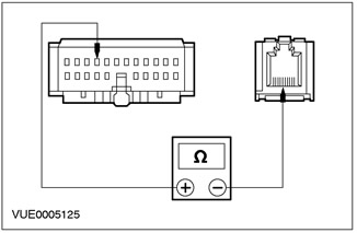
3 Using a digital multimeter, measure the resistance between pin 21 C463 of the handheld support module, circuit 1 - MD52 (white/red), on the wiring side, and pin 9 C447 of the audio unit, circuit 1 - MD52 (white/red), from the side of the electrical wiring. |
|
• Is the resistance less than 5 ohms? |
|
|
→ Yes |
|
|
Go to E3 Go to PINPOINT TEST E |
|
|
→ No |
|
|
Repair the electrical circuit. CHECK the system is working properly. |
|
|
E3: CHECK CIRCUIT 8 - MD52 FOR OPEN |
|
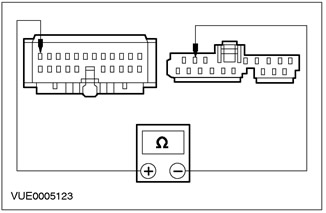 |
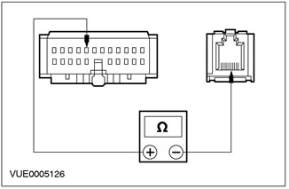
1 Using a digital multimeter, measure the resistance between pin 22 C463 of the handheld support module, circuit 8 - MD52 (white/red), on the wiring side, and pin 8 C447 of the audio unit, electrical circuit 8 - MD52 (white/red), from the side of the electrical wiring. |
|
• Is the resistance less than 5 ohms? |
|
|
→ Yes |
|
|
INSTALL the new portable support module. CHECK the system is working properly. |
|
|
→ No |
|
|
REPAIR the electrical circuit. CHECK the system is working properly. |
|
PINPOINT TEST F: CELL PHONE MESSAGES DO NOT DISPLAY ON AUDIO UNIT DISPLAY
|
STATES |
DETAILS/RESULTS/ACTIONS |
|
F1: CHECK CELL PHONE OUTSIDE VEHICLE FUNCTIONING |
|
|
1 Use your cell phone while outside the vehicle. |
|
|
• Does the cell phone function properly outside the vehicle? |
|
|
→ Yes |
|
|
Go to F2 Go to PINPOINT TEST F |
|
|
→ No |
|
|
CONTACT a Motorola Service Center. CHECK the system is working properly. |
|
|
F2: CHECK 91S-MC19 CIRCUIT FOR OPEN |
|
|
1 Disconnect the Handheld Support Module - C463. |
|
|
2 Disconnect the Tube Bracket - C471. |
|
|
3 Using a digital multimeter, measure the resistance between pin 20 C463 of the handheld support module, circuit 91S - MC19 (black/green), wiring side, and pin 7 C471 of tube bracket, circuit 91S - MC19 (black/green), from the side of the electrical wiring. |
|
• Is the resistance less than 5 ohms? |
|
|
→ Yes |
|
|
Go to F3 Go to PINPOINT TEST F |
|
|
→ No |
|
|
REPAIR the electrical circuit. CHECK the system is working properly. |
|
|
F3: CHECK 5-MC20 CIRCUIT FOR OPEN |
|
|
1 Using a digital multimeter, measure the resistance between pin 19 C463 of the handheld support module, circuit 5 - MC20 (blue/yellow), wiring side, and pin 6 C471 of tube bracket, electrical circuit 5 - MC20 (blue/yellow), from the side of the electrical wiring. |
|
• Is the resistance less than 5 ohms? |
|
|
→ Yes |
|
|
Go to F4 Go to PINPOINT TEST F |
|
|
→ No |
|
|
Repair the electrical circuit. CHECK the system is working properly. |
|
|
F4: CHECK CIRCUIT 4-MC21 FOR OPEN |
|
|
1 Using a digital multimeter, measure the resistance between pin 18 C463 of the handheld support module, circuit 4 - MC21 (grey/white), wiring side, and pin 5 C471 of tube bracket, circuit 4 - MC21 (grey/white), from the side of the electrical wiring. |
|
• Is the resistance less than 5 ohms? |
|
|
→ Yes |
|
|
Go to F5 Go to PINPOINT TEST F |
|
|
→ No |
|
|
REPAIR the electrical circuit. CHECK the system is working properly. |
|
|
F5: CHECK CIRCUIT 5-EA10 FOR OPEN |
|
|
1 Disconnect the Audio Unit - C447. |
|
|
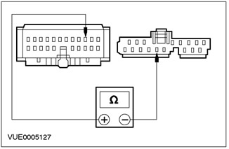
2 Using a digital multimeter, measure the resistance between pin 13 C463 of the handheld support module, circuit 5 - EA10 (blue/yellow), on the wiring side, and pin 2 C447 of the audio unit, circuit 5 - EA10 (blue/yellow), from the side of the electrical wiring. |
|
• Is the resistance less than 5 ohms? |
|
|
→ Yes |
|
|
Go to F6 Go to PINPOINT TEST F |
|
|
→ No |
|
|
REPAIR the electrical circuit. CHECK the system is working properly. |
|
|
F6: CHECK CIRCUIT 4-EA10 FOR OPEN |
|
|
1 Using a digital multimeter, measure the resistance between C463 pin 12 of the handheld support module, circuit 4 - EA10 (gray/black), on the wiring side, and pin 1 C447 of the audio unit, circuit 4 - EA10 (gray/black), from the side of the electrical wiring. |
|
• Is the resistance less than 5 ohms? |
|
|
→ Yes |
|
|
Go to A6 |
|
|
→ No |
|
|
Repair the electrical circuit. CHECK the system is working properly. |
|
Visitor comments