Operating principle
NOTE: After installing a new Generic Electronic Module (GEM), its configuration must be configured. Refer to Section 418-01 for more information.
GEM constantly monitors all subsystems for problems. If a problem is detected in one of the subsystems, GEM will record information about the problem in the form of a diagnostic trouble code (DTC). The position of the ignition switch is very important to the function of GEM. Often, erratic or unexpected operation of GEM can be traced to problems related to the input signals of the ignition switch.
Inspection and verification
1. Check the customer complaint.
2. Visually inspect for obvious signs of electrical damage.
Visual inspection table
Electrical factors:
- Central Junction Box (CJB) Fuse(s)
- Wiring harness
- Plug connector(s).
- Electrical circuit(s)
3. If the problem persists after inspection, connect the diagnostic connector to the Data Link Connector (DLC) located under the instrument panel and select the vehicle being tested from the diagnostic tool menu. If the diagnostic tool does not communicate with the vehicle:
- check if the software card is installed correctly.
- check the connections going to the car.
- check the position of the ignition switch.
4. If the scan tool still does not communicate with the vehicle, refer to the scan tool service manual.
5. Perform the DATA LINK diagnostic check. If the scan tool responds:
- CKT914, CKT915 or CKT70 = ALL ECUS NO RESP/NOT EQUIP, Refer to Section 418-00 for additional information.
- NO RESPONSE/NOT EQUIP for GEM, Proceed to PINPOINT TEST E.
- SYSTEM PASSED, retrieve and record permanent diagnostic trouble codes (DTCs), clear permanent DTCs, and perform the GEM self-test diagnostics.
6. If the retrieved DTCs are related to the problem, go to the Diagnostic Trouble Code (DTC) Index.
7. If no DTCs related to the problem are retrieved, refer to the appropriate section of the Service Manual to continue diagnostics.
Diagnostic Trouble Code (DTC) Table
|
DTC |
Name |
Cause |
Actions |
|
B1202 |
Fuel sensor electrical circuit open |
Instrument panel |
For additional information, see Section 413-01. |
|
B1204 |
Short circuit of the fuel sensor electrical circuit to ground |
Instrument panel |
For additional information, see Section 413-01. |
|
B1231 |
Longitudinal acceleration threshold exceeded |
Restraint Control Module (RCM) |
For additional information, please refer to Section 501-20A/501-20B. |
|
B1244 |
Rear window wiper motor relay circuit malfunction |
GEM |
For more information, see Section 501-16. |
|
B1245 |
Short circuit to + battery of the electrical circuit of the rear window wiper motor relay |
GEM |
For more information, see Section 501-16. |
|
B1300 |
Electrical circuit malfunction of the power door lock |
GEM |
For more information, see Section 501-14. |
|
B1309 |
Short circuit of the electrical circuit of the electric door lock to ground |
GEM |
For more information, see Section 501-14. |
|
B1310 |
Malfunction of the electrical circuit of the power door release |
GEM |
For more information, see Section 501-14. |
|
B1315 |
Short circuit to ground in the electrical circuit of the battery energy saving device relay coil |
GEM |
For additional information, see Section 417-02. |
|
B1316 |
Short circuit to ground in the electrical circuit of the battery energy saving device relay coil |
GEM |
For additional information, see Section 417-02. |
|
B1317 |
High battery voltage |
Instrument panel |
For additional information, see Section 414-01. |
|
B1317 |
High battery voltage |
Anti-lock Brake System (ABS) Module |
For additional information, see Section 414-01. |
|
B1318 |
Low battery voltage |
Instrument panel |
For additional information, see Section 414-01. |
|
B1318 |
Low battery voltage |
RCM |
For additional information, see Section 414-01. |
|
B1318 |
Low battery voltage |
ABS module |
For additional information, see Section 414-01. |
|
B1319 |
Malfunction of the electrical circuit of the door not closing tightly |
GEM |
For additional information, see Section 417-02. |
|
B1325 |
Short circuit to ground in the electrical circuit of the door ajar lamp |
GEM |
For additional information, see Section 417-02. |
|
B1326 |
Short circuit to ground in the electrical circuit of the door ajar lamp |
GEM |
For additional information, see Section 417-02. |
|
B1327 |
Malfunction of the electrical circuit of the passenger door not closing tightly |
GEM |
For additional information, see Section 417-02. |
|
B1331 |
Malfunction of the electrical circuit of the trunk lid not closing tightly |
GEM |
For additional information, see Section 417-02. |
|
B1335 |
Right rear door loose closing circuit fault |
GEM |
For additional information, see Section 417-02. |
|
B1341 |
Short circuit to ground in the electrical circuit for unlocking the electric door with an electric drive |
GEM |
For more information, see Section 501-14. |
|
B1342 |
The instrument panel is faulty |
Instrument panel |
CLEAR the DTCs. REPEAT the self-test. If DTC B1342 is retrieved, INSTALL a new instrument cluster. Refer to Section 413-01 for additional information. CLEAR the DTCs. REPEAT the self-test. |
|
B1342 |
RCM is faulty |
RCM |
CLEAR the DTCs. REPEAT the self-test. If DTC B1342 is retrieved, INSTALL a new RCM. Refer to Section 501-20A / 501-20B for additional information. CLEAR the DTCs. REPEAT the self-test. |
|
B1342 |
ABS module is faulty |
ABS module. |
CLEAR the DTCs. REPEAT the self-test. If DTC B1342 is retrieved, INSTALL a new ABS module. Refer to Section 206-09A / 206-09B / 206-09C for additional information. CLEAR the DTCs. REPEAT the self-test. |
|
B1342 |
GEM is faulty |
GEM |
CLEAR the DTCs. REPEAT the self-test. If DTC B1342 is retrieved, INSTALL a new GEM. REFER to the General Electronic Module section in this section. CLEAR the DTCs. REPEAT the self-test. |
|
B1343 |
Rear window defroster input circuit electrical fault |
GEM |
For more information, see Section 501-11. |
|
B1349 |
Short circuit to + battery of the electrical circuit of the rear window heating relay |
GEM |
For more information, see Section 501-11. |
|
B1350 |
Short circuit to ground in the electrical circuit of the rear window heating relay |
GEM |
For more information, see Section 501-11. |
|
B1352 |
Key-in-ignition circuit malfunction |
GEM |
For additional information, see Section 413-09. |
|
B1359 |
Ignition Run/Acc (Run/Accessories) Circuit Malfunction |
Instrument panel |
For additional information, see Section 413-01. |
|
B1426 |
Short circuit to battery + in the electrical circuit of the seat belt warning lamp |
GEM |
For additional information, see Section 413-00. |
|
B1428 |
Seat belt warning light electrical circuit malfunction |
GEM |
For additional information, see Section 413-00. |
|
B1438 |
Windscreen wiper mode selector switch electrical circuit malfunction |
GEM |
For more information, see Section 501-16. |
|
B1446 |
Malfunction of the electrical circuit for sensing the parking position of the windshield wipers |
GEM |
For more information, see Section 501-16. |
|
B1451 |
Wiper/washer delay switch electrical circuit malfunction |
GEM |
For more information, see Section 501-16. |
|
B1462 |
Seat belt switch malfunction |
RCM |
For additional information, please refer to Section 501-20A/501-20B. |
|
B1470 |
Malfunction of the electrical circuit of the input signal of the headlight indicator lamp |
GEM |
For additional information, see Section 417-01. |
|
B1499 |
Left turn signal indicator lamp electrical circuit malfunction |
GEM |
For additional information, see Section 417-01. |
|
B1503 |
Right turn signal indicator lamp electrical circuit malfunction |
GEM |
For additional information, see Section 417-01. |
|
B1519 |
Hood switch electrical circuit malfunction |
GEM |
For additional information, refer to Section 419-01A/419-01B. |
|
B1549 |
Short circuit to + battery of the main switch of the electric drive of the lifts |
GEM |
For more information, see Section 501-11. |
|
B1550 |
Short circuit to ground of the main switch of the electric drive of the lifts |
GEM |
For more information, see Section 501-11. |
|
B1551 |
Malfunction of the electrical circuit of the trunk lid release |
GEM |
For more information, see Section 501-14. |
|
B1553 |
Short circuit to + battery of the electrical circuit for unlocking the trunk lid |
GEM |
For more information, see Section 501-14. |
|
B1554 |
Short circuit to ground in the trunk lid release electrical circuit |
GEM |
For more information, see Section 501-14. |
|
B1571 |
Left rear door loose closing circuit fault |
GEM |
For additional information, see Section 417-02. |
|
B1611 |
Rear window wiper mode selector switch malfunction |
GEM |
For more information, see Section 501-16. |
|
B1810 |
Malfunction of the electrical circuit of the input signal of the reverse light switch |
GEM |
For additional information, see Section 417-01. |
|
B1869 |
Open circuit of airbag warning lamp |
RCM |
For additional information, please refer to Section 501-20A/501-20B. |
|
B1870 |
Short circuit to battery + in the airbag warning lamp electrical circuit |
RCM |
For additional information, please refer to Section 501-20A/501-20B. |
|
B1871 |
Passenger airbag deactivation module malfunction |
RCM |
For additional information, please refer to Section 501-20A/501-20B. |
|
B1875 |
Malfunction of the turn signal/hazard warning switch electrical circuit |
GEM |
For additional information, see Section 417-01. |
|
B1876 |
Driver's seat belt pretensioner electrical circuit malfunction |
GEM |
For additional information, please refer to Section 501-20A/501-20B. |
|
B1876 |
Driver's seat belt pretensioner electrical circuit malfunction |
RCM |
For additional information, please refer to Section 501-20A/501-20B. |
|
B1877 |
Driver's seat belt tensioner electrical circuit open |
RCM |
For additional information, please refer to Section 501-20A/501-20B. |
|
B1878 |
Short circuit to battery + in the electrical circuit of the driver's seat belt tensioner |
RCM |
For additional information, please refer to Section 501-20A/501-20B. |
|
B1880 |
Passenger seat belt pretensioner electrical circuit malfunction |
RCM |
For additional information, please refer to Section 501-20A/501-20B. |
|
B1881 |
Open circuit of the passenger seat belt tensioner |
RCM |
For additional information, please refer to Section 501-20A/501-20B. |
|
B1882 |
Short circuit to battery + in the electrical circuit of the passenger seat belt tensioner |
RCM |
For additional information, please refer to Section 501-20A/501-20B. |
|
B1885 |
Driver Seat Belt Pretensioner Igniter Circuit Low Resistance |
RCM |
For additional information, please refer to Section 501-20A/501-20B. |
|
B1886 |
Passenger Seat Belt Pretensioner Igniter Circuit Low Resistance |
RCM |
For additional information, please refer to Section 501-20A/501-20B. |
|
B1915 |
Driver airbag electrical circuit malfunction |
RCM |
For additional information, please refer to Section 501-20A/501-20B. |
|
B1916 |
Short circuit to battery + in the driver's airbag electrical circuit |
RCM |
For additional information, please refer to Section 501-20A/501-20B. |
|
B1920 |
Passenger airbag electrical circuit malfunction |
RCM |
For additional information, please refer to Section 501-20A/501-20B. |
|
B1925 |
Short circuit to battery + in passenger airbag electrical circuit |
RCM |
For additional information, please refer to Section 501-20A/501-20B. |
|
B1932 |
Driver's airbag electrical circuit open |
RCM |
For additional information, please refer to Section 501-20A/501-20B. |
|
B1933 |
Passenger airbag electrical circuit open |
RCM |
For additional information, please refer to Section 501-20A/501-20B. |
|
B1934 |
Driver Air Bag Inflator Igniter Circuit Low Resistance |
RCM |
For additional information, please refer to Section 501-20A/501-20B. |
|
B1935 |
Passenger Air Bag Inflator Igniter Circuit Low Resistance |
RCM |
For additional information, please refer to Section 501-20A/501-20B. |
|
B1936 |
Short circuit to ground in the driver airbag electrical circuit |
RCM |
For additional information, please refer to Section 501-20A/501-20B. |
|
B1938 |
Short circuit to ground in the passenger airbag electrical circuit |
RCM |
For additional information, please refer to Section 501-20A/501-20B. |
|
B1992 |
Short circuit to battery + in the electrical circuit of the side airbag on the driver's side |
RCM |
For additional information, please refer to Section 501-20A/501-20B. |
|
B1993 |
Short circuit to ground in the electrical circuit of the driver's side airbag |
RCM |
For additional information, please refer to Section 501-20A/501-20B. |
|
B1994 |
Driver side airbag electrical circuit open |
RCM |
For additional information, please refer to Section 501-20A/501-20B. |
|
B1995 |
Low resistance of the driver's side airbag igniter electrical circuit |
RCM |
For additional information, please refer to Section 501-20A/501-20B. |
|
B1996 |
Short circuit to battery + in the electrical circuit of the side airbag on the passenger side |
RCM |
For additional information, please refer to Section 501-20A/501-20B. |
|
B1997 |
Short circuit to ground in the passenger side airbag electrical circuit |
RCM |
For additional information, please refer to Section 501-20A/501-20B. |
|
B1998 |
Driver side airbag electrical circuit open |
RCM |
For additional information, please refer to Section 501-20A/501-20B. |
|
B1999 |
Low resistance of the driver's side airbag igniter electrical circuit |
RCM |
For additional information, please refer to Section 501-20A/501-20B. |
|
B2107 |
Short circuit to + battery in the electrical circuit of the windshield wiper motor relay |
GEM |
For more information, see Section 501-16. |
|
B2108 |
Trunk lock cylinder switch malfunction |
GEM |
For more information, see Section 501-14. |
|
B2110 |
Windshield wiper motor relay open circuit |
GEM |
For more information, see Section 501-16. |
|
B2112 |
Malfunction consisting of jamming of the driver's door setting switch |
GEM |
For more information, see Section 501-14. |
|
B2113 |
Short circuit to ground in the electrical circuit of the input signal of the heated windshield |
GEM |
For more information, see Section 501-16. |
|
B2114 |
Short circuit to ground in the windshield washer input signal circuit |
GEM |
For more information, see Section 501-16. |
|
B2115 |
Short circuit to ground on rear window washer input signal |
GEM |
For more information, see Section 501-16. |
|
B2116 |
Malfunction consisting of jamming of the driver's door reset switch |
GEM |
For more information, see Section 501-14. |
|
B2117 |
Driver side airbag igniter capacity low |
RCM |
For additional information, please refer to Section 501-20A/501-20B. |
|
B2118 |
Passenger side airbag igniter capacity low |
RCM |
For additional information, please refer to Section 501-20A/501-20B. |
|
B2141 |
NVM memory error |
RCM |
For additional information, please refer to Section 501-20A/501-20B. |
|
B2143 |
NVM memory error |
Instrument panel |
For additional information, see Section 413-01. |
|
B2226 |
Internal fault of front impact sensor |
RCM |
For additional information, please refer to Section 501-20A/501-20B. |
|
B2227 |
Malfunction in data transmission to the driver from the front impact sensor |
RCM |
For additional information, please refer to Section 501-20A/501-20B. |
|
B2228 |
Short circuit to ground in the driver airbag electrical circuit - Circuit No.2 |
RCM |
For additional information, please refer to Section 501-20A/501-20B. |
|
B2229 |
Short circuit to ground in the passenger airbag electrical circuit - Circuit No.2 |
RCM |
For additional information, please refer to Section 501-20A/501-20B. |
|
B2230 |
Short circuit to + battery in the electrical circuit of the driver's airbag - Circuit No.2 |
RCM |
For additional information, please refer to Section 501-20A/501-20B. |
|
B2231 |
Short circuit to ground in the passenger airbag electrical circuit - Circuit No.2 |
RCM |
For additional information, please refer to Section 501-20A/501-20B. |
|
B2232 |
Driver Airbag Circuit Open - Circuit #2 |
RCM |
For additional information, please refer to Section 501-20A/501-20B. |
|
B2233 |
Passenger Airbag Circuit Open - Circuit #2 |
RCM |
For additional information, please refer to Section 501-20A/501-20B. |
|
B2234 |
Driver Air Bag Inflator Igniter Circuit Low Resistance - Circuit #2 |
RCM |
For additional information, please refer to Section 501-20A/501-20B. |
|
B2235 |
Passenger Air Bag Inflator Igniter Circuit Low Resistance - Circuit #2 |
RCM |
For additional information, please refer to Section 501-20A/501-20B. |
|
B2248 |
Windshield heating relay coil electrical circuit malfunction |
GEM |
For more information, see Section 501-11. |
|
B2256 |
Short circuit to ground in the electrical circuit of the windshield heating relay |
GEM |
For more information, see Section 501-11. |
|
B2279 |
Short circuit to battery + of the engine run signal electrical circuit |
GEM |
Refer to the Powertrain Diagnostics (PC/ED) Guide. |
|
B2281 |
Short circuit to ground in right turn signal switch |
GEM |
For additional information, see Section 417-01. |
|
B2282 |
Short circuit to ground in left turn signal switch |
GEM |
For additional information, see Section 417-01. |
|
B2283 |
Short circuit to + battery of the turn signal horn |
GEM |
For additional information, see Section 417-01. |
|
B2284 |
Short circuit to ground of the turn signal horn |
GEM |
For additional information, see Section 417-01. |
|
B2369 |
Short circuit to ground of the horn request |
GEM |
For additional information, please refer to Section 501-20A/501-20B. |
|
B2433 |
Short circuit to battery + in electrical circuit of driver's seat belt buckle switch |
RCM |
For additional information, please refer to Section 501-20A/501-20B. |
|
B2434 |
Short circuit to ground in the electrical circuit of the driver's seat belt buckle switch |
RCM |
For additional information, please refer to Section 501-20A/501-20B. |
|
B2435 |
Driver seat belt buckle switch circuit resistance out of operating range |
RCM |
For additional information, please refer to Section 501-20A/501-20B. |
|
B2437 |
Short circuit to battery + in the electrical circuit of the passenger seat belt buckle switch |
RCM |
For additional information, please refer to Section 501-20A/501-20B. |
|
B2438 |
Short circuit to ground in the electrical circuit of the passenger seat belt buckle switch |
RCM |
For additional information, please refer to Section 501-20A/501-20B. |
|
B2439 |
Passenger seat belt buckle switch circuit resistance out of operating range |
RCM |
For additional information, please refer to Section 501-20A/501-20B. |
|
B2477 |
Module configuration error |
Instrument panel |
For additional information, see Section 418-01. |
|
B2477 |
Module configuration error |
RCM |
For additional information, see Section 418-01. |
|
B2494 |
Short circuit to + battery of the electrical circuit of the output signal of the sound signal of the anti-theft alarm |
GEM |
For additional information, refer to Section 419-01A/419-01B. |
|
B2496 |
Short circuit to ground in the electrical circuit of the output signal of the sound signal of the anti-theft alarm |
GEM |
For additional information, refer to Section 419-01A/419-01B. |
|
B2555 |
Short circuit to battery + of the electrical circuit of the output signal of the ceiling lamp |
GEM |
For additional information, see Section 417-02. |
|
B2852 |
Short circuit to ground/+ battery in the electrical circuit of the right additional sensor |
RCM |
For additional information, please refer to Section 501-20A/501-20B. |
|
B2853 |
Short circuit to ground/+ battery in the electrical circuit of the left additional sensor |
RCM |
For additional information, please refer to Section 501-20A/501-20B. |
|
B2854 |
Left Impact Sensor Identification Malfunction |
RCM |
For additional information, please refer to Section 501-20A/501-20B. |
|
B2855 |
Short circuit to ground/+ battery in front impact sensor electrical circuit |
RCM |
For additional information, please refer to Section 501-20A/501-20B. |
|
B2856 |
Front Impact Sensor Identification Malfunction |
RCM |
For additional information, please refer to Section 501-20A/501-20B. |
|
B2873 |
Internal malfunction of the left impact sensor |
RCM |
For additional information, please refer to Section 501-20A/501-20B. |
|
B2874 |
Internal malfunction of the right impact sensor |
RCM |
For additional information, please refer to Section 501-20A/501-20B. |
|
B2875 |
Right Impact Sensor Identification Malfunction |
RCM |
For additional information, please refer to Section 501-20A/501-20B. |
|
C1095 |
ABS hydraulic pump motor electrical circuit fault |
ABS module |
For additional information, see Section 206-09A/206-09B/206-09C. |
|
C1141 |
Malfunction consisting of missing teeth on the left front wheel speed sensor pulse wheel |
ABS module |
For additional information, see Section 206-09A/206-09B/206-09C. |
|
C1142 |
Malfunction consisting of missing teeth on the pulse wheel of the right front wheel speed sensor |
ABS module |
For additional information, see Section 206-09A/206-09B/206-09C. |
|
C1143 |
Malfunction consisting of missing teeth on the left rear wheel speed sensor pulse wheel |
ABS module |
For additional information, see Section 206-09A/206-09B/206-09C. |
|
C1144 |
Malfunction consisting of missing teeth on the pulse wheel of the right rear wheel speed sensor |
ABS module |
For additional information, see Section 206-09A/206-09B/206-09C. |
|
C1145 |
Right Front Wheel Speed Input Signal Circuit Malfunction |
ABS module |
For additional information, see Section 206-09A/206-09B/206-09C. |
|
C1155 |
Left Front Wheel Speed Input Signal Circuit Malfunction |
ABS module |
For additional information, see Section 206-09A/206-09B/206-09C. |
|
C1165 |
Right Rear Wheel Speed Input Signal Circuit Malfunction |
ABS module |
For additional information, see Section 206-09A/206-09B/206-09C. |
|
C1175 |
Left Rear Wheel Speed Input Signal Circuit Malfunction |
ABS module |
For additional information, see Section 206-09A/206-09B/206-09C. |
|
C1233 |
No Left Front Wheel Speed Input Signal |
ABS module |
For additional information, see Section 206-09A/206-09B/206-09C. |
|
C1234 |
No input signal for right front wheel speed, |
ABS module |
For additional information, see Section 206-09A/206-09B/206-09C. |
|
C1235 |
No Right Rear Wheel Speed Input Signal |
ABS module |
For additional information, see Section 206-09A/206-09B/206-09C. |
|
C1236 |
No Left Rear Wheel Speed Input Signal |
ABS module |
For additional information, see Section 206-09A/206-09B/206-09C. |
|
C1267 |
Temporary disabling of ABS functions |
ABS module |
For additional information, see Section 206-09A/206-09B/206-09C. |
|
C1277 |
Malfunction of electrical circuits 1 and 2 of steering wheel rotation angle |
ABS module |
For additional information, see Section 206-09A/206-09B/206-09C. |
|
C1278 |
Steering wheel angle 1 and 2 signal failure |
ABS module |
For additional information, see Section 206-09A/206-09B/206-09C. |
|
C1279 |
Yaw rate sensor electrical circuit malfunction |
ABS module |
For additional information, see Section 206-09A/206-09B/206-09C. |
|
C1280 |
Failure in the signal supply of the yaw rate sensor |
ABS module |
For additional information, see Section 206-09A/206-09B/206-09C. |
|
C1281 |
Transverse accelerometer electrical circuit malfunction |
ABS module |
For additional information, see Section 206-09A/206-09B/206-09C. |
|
C1282 |
Transverse accelerometer signal failure |
ABS module |
For additional information, see Section 206-09A/206-09B/206-09C. |
|
C1288 |
Main pressure sensor input signal circuit malfunction |
ABS module |
For additional information, see Section 206-09A/206-09B/206-09C. |
|
C1730 |
Reference voltage out of working range (+5V) |
ABS module |
For additional information, see Section 206-09A/206-09B/206-09C. |
|
C1947 |
Short circuit to ground in seat guide switch electrical circuit |
RCM |
For additional information, please refer to Section 501-20A/501-20B. |
|
C1948 |
Seat Track Position Switch Circuit Resistance Out of Operating Range |
RCM |
For additional information, please refer to Section 501-20A/501-20B. |
|
C1982 |
Short circuit to battery + in seat guide switch electrical circuit |
RCM |
For additional information, please refer to Section 501-20A/501-20B. |
|
P1197 |
Malfunction of the electrical circuit of the mileage switch |
Instrument panel |
For additional information, see Section 413-01. |
|
P1778 |
Incorrect operation of the transmission I/P reverse electrical circuit |
GEM |
For additional information, see Section 413-01. |
|
U1009 |
Invalid or missing SCP (J1850) bus data for engine torque |
ABS module |
For additional information, see Section 206-09A/206-09B/206-09C. |
|
U1027 |
Invalid or missing data for engine speed |
Instrument panel |
Refer to the Powertrain Diagnostics (PC/ED) Guide. |
|
U1027 |
Invalid or missing SCP (J1850) bus data for engine speed |
ABS module |
Refer to the Powertrain Diagnostics (PC/ED) Guide. |
|
U1041 |
Invalid or missing vehicle speed data |
Instrument panel |
Refer to the Powertrain Diagnostics (PC/ED) Guide. |
|
U1073 |
Invalid or missing engine coolant data |
Instrument panel |
Refer to the Powertrain Diagnostics (PC/ED) Guide. |
|
U1123 |
Invalid or missing data for odometer |
Instrument panel |
For additional information, see Section 413-01. |
|
U1262 |
Data bus failure |
Instrument panel |
For additional information, see Section 418-00. |
|
U2027 |
Left Impact Sensor Data Transmission Malfunction (Non-SCP) |
RCM |
For additional information, please refer to Section 501-20A/501-20B. |
|
U2028 |
Right Impact Sensor Data Transmission Malfunction (Non-SCP) |
RCM |
For additional information, please refer to Section 501-20A/501-20B. |
Table of signs of malfunction
|
State |
Possible Causes |
Action |
|
•No communication with the General Electronic Module (GEM) |
•CJB fuse(s) •Electrical circuit(s). • GEM |
• Proceed to PINPOINT TEST E. |
PINPOINT TEST E: NO COMMUNICATION WITH GENERAL ELECTRONIC MODULE (GEM)
|
STATES |
DETAILS/RESULTS/ACTIONS |
|
E1: CHECK IGNITION STATUS - MONITORING PID GEM PARAMETERS: IGN_A, IGN_O/L, IGN_R, AND IGN_S |
|
|
1Enter the OFF position. |
|
|
2Connect the diagnostic tool. |
|
|
3Monitor GEM PIDs: IGN_A, IGN_O/L, IGN_R, and IGN_S as you rotate the ignition switch through the START, RUN, OFF, and ACC positions. |
|
|
• Do the GEM PID values match the ignition switch positions? |
|
|
→ Yes |
|
|
Go to E2. |
|
|
→ No |
|
|
REPAIR the ignition circuit in question (RUN/ACC: circuit 155-AA17 (BK/YE), KEY IN: B 305-TA31A (RED/BLK), Idle Position circuit 315-TA3232 (BK/WH)). CLEAR the DTCs. REPEAT the self-test. |
|
|
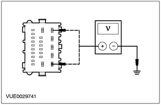
E2: CHECK ELECTRICAL CIRCUIT 29-DK20 (ORANGE/GREEN) AND ELECTRICAL CIRCUIT 29-M11 (ORANGE/WHITE) FOR VOLTAGE |
|
|
1Enter the OFF position. |
|
|
2Disconnect C103 GEM.. |
|
|
3Measure the voltage between pin 5 of GEM connector C103, circuit 29-DK20 (OG/GN), harness side and ground, and pin 1 of GEM connector C103, circuit 29-AA17 (OG/WH), harness side and ground. |
|
• Is the voltage greater than 10 V? |
|
|
→ Yes |
|
|
Go to E3. |
|
|
→ No |
|
|
REPAIR the power supply circuits. CLEAR the DTCs. REPEAT the self-test. |
|
|
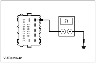
E3: CHECKING THE GEM 31-DK20 (BLACK) ELECTRICAL CIRCUIT FOR OPEN |
|
|
1Disconnect C101 GEM. |
|
|
2Measure the resistance between pin 5 of the GEM connector C101, circuit 31-DK20 (black), harness side, and ground. |
|
• Resistance less than 5 ohms? |
|
|
→ Yes |
|
|
Go to E4. |
|
|
→ No |
|
|
REPAIR the electrical circuit. CLEAR the DTCs. REPEAT the self-test. |
|
|
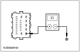
E4: CHECKING THE GEM 91-DK20 (BLACK/RED) ELECTRICAL CIRCUIT FOR OPEN |
|
|
1Measure the resistance between pin 1 of GEM connector C104, circuit 91-DK20 (black/red), harness side, and ground. |
|
• Resistance less than 5 ohms? |
|
|
→ Yes |
|
|
INSTALL a new GEM. REFER to the General Electronic Module section in this section. CLEAR the DTCs. REPEAT the self-test. |
|
|
→ No |
|
|
REPAIR the electrical circuit. CLEAR the DTCs. REPEAT the self-test. |
|