|
STATES |
DETAILS/RESULTS/ACTIONS |
|
A1: CSM INPUT AND OUTPUT SELF-TEST |
|
|
1 Make sure the doors, tailgate/lid and hood are fully open |
|
|
2 Perform a CSM self-test. For more information, refer to the Self Test available in this section.. |
|
|
• Are all input signals tested correct? |
|
|
→ Yes |
|
|
For vehicles with interior scan function, Go to A2 For vehicles without interior sanitization function, RECOVER DTCs. If there are no DTCs, CHECK the system for proper operation. |
|
|
→ No |
|
|
If the anti-theft alarm does not sound when the hood is opened, Go to A6 |
|
|
If the anti-theft alarm does not sound, Go to A9 |
|
|
If the turn signal lamps do not flash, Go to A11 |
|
|
If there is no response signal: |
|
|
Remote Transmitter Refer to Section 501-14 for more information. |
|
|
Door control with key (on/off switch), Go to A13 |
|
|
Interior lamp door switch (on/off switch), Go to A18 |
|
|
Tailgate control with key (on/off switch), Go to A19 |
|
|
Rear Tailgate Interior Lamp Switch Go to A22 |
|
|
A2: INTERIOR SCAN SENSORS CHECK |
|
|
1 Partially roll down the left door glass, then turn on the anti-theft system. |
|
|
2 Wait approximately one minute, then move your hand over the left scanning sensor. |
|
|
3 Raise the glass of the left door. Partially lower the right door glass, then turn on the anti-theft system. |
|
|
4 Wait approximately one minute, then move your hand over the right scanning sensor. |
|
|
• The alarm was turned off by the command of each of the sensors? |
|
|
→ Yes |
|
|
RECOVER DTCs. CHECK the system is working properly. |
|
|
→ No |
|
|
Go to A3 |
|
|
A3: CHECKING THE WIRING OF INTERIOR SCAN SENSORS |
|
|
1 Disconnect the C452 of the CSM. |
|
|
2 Disconnect C453 Left Interior Scan Sensor. |
|
|
3 Disconnect C454 right interior scan sensor. |
|
|
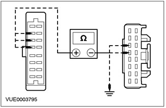
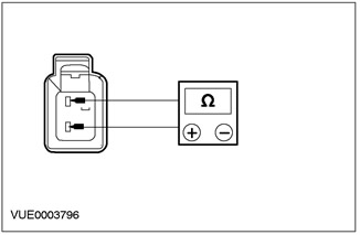
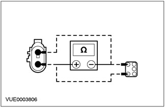
4 Measure the resistance between pin 6 of C453 interior scan sensor connector, circuit 8-GL10 (white), from the wiring side, and pin 14 of the C452 CSM connector, electrical circuit 8-GL10 (white), from the side of the electrical wiring. - Measure the resistance between pin 7 of connector C453 of the interior scan sensor, circuit 7-GL10 (yellow), wiring side, and pin 13 of connector C452 CSM, circuit 7-GL1 (yellow), from the side of the electrical wiring. - Measure the resistance between pin 5 of connector C453 of the interior scan sensor, circuit 31-GL10 (black), from the wiring side, and "ground". |
|
• Is the resistance always less than 5 ohms? |
|
|
→ Yes |
|
|
Go to A4 |
|
|
→ No |
|
|
REPAIR or INSTALL new interior scan sensor wiring. CHECK the system is working properly. |
|
|
A4: INTERIOR SCAN SENSOR WIRING CHECK |
|
|
1 Measure the resistance between pin 15 of the interior scan sensor connector C454, circuit 31-GL17 (black), from the wiring side, and "ground". - Measure the resistance between pin 2 of connector C454 of the interior scan sensor, circuit 7-GL17 (yellow-red), wiring side, and pin 13 of connector C452 CSM, circuit 7-GL1 (yellow), from the side of the electrical wiring. |
|
• Is the resistance always less than 5 ohms? |
|
|
→ Yes |
|
|
Go to A5 |
|
|
→ No |
|
|
REPAIR or INSTALL new interior scan sensor wiring. CHECK the system is working properly. |
|
|
A5: INTERIOR SCAN SENSOR WIRING CHECK |
|
|
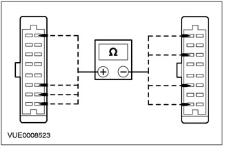
1 Measure the resistance between pin 1 (gray), pin 3 (blue), pin 14 (grey-red), pin 16 (red-blue) connector C454 of the interior scan sensor, wiring side, and pin 8 (gray), pin 9 (blue), pin 10 (grey-red) and pin 11 (red-blue) connector C453 of the interior scan sensor, wiring side. |
|
• Is the resistance always less than 5 ohms? |
|
|
→ Yes |
|
|
RECOVER DTCs. If there are no DTCs, CHECK the system is operating correctly. If the problem persists, INSTALL a new interior scan sensor. CHECK the system is working properly. |
|
|
→ No |
|
|
REPAIR or INSTALL new interior scan sensor wiring. CHECK the system is working properly. |
|
|
A6: SIGNAL TEST FROM HOOD SWITCH TO CSM |
|
|
1 Disconnect the C452 of the CSM. |
|
|
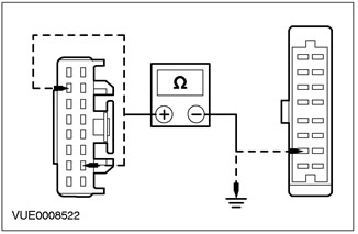
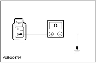
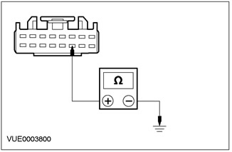
2 Measure the resistance between pin 3 of connector C452 CSM, circuit 31S-GL7A (black and yellow), from the wiring side, and "ground". Take readings with the hood closed and with the hood open. |
|
• Is the resistance less than 5 ohms with the hood closed and more than 10,000 ohms with the hood open? |
|
|
→ Yes |
|
|
RECOVER DTCs. If there are no DTCs, CHECK the system is operating correctly. If the problem persists, INSTALL a new CSM, See Section 419-10 for more information. CHECK the system is working properly. |
|
|
→ No |
|
|
Go to A8 |
|
|
A7: CHECK THE HOOD SWITCH |
|
|
1 Disconnect the C897 hood switch. |
|
|
2 Measure the resistance between pins 1 and 2 of connector C897 of the hood switch, element side. Take readings with the switch stem depressed and not depressed. |
|
• Is the resistance less than 5 ohms with the switch stem not depressed and more than 10,000 ohms with the switch stem depressed? |
|
|
→ Yes |
|
|
Go to A8 |
|
|
→ No |
|
|
INSTALL a new hood switch. CHECK the system is working properly. |
|
|
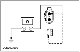
A8: HOOD SWITCH GROUND CHECK |
|
|
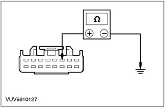
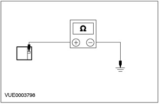
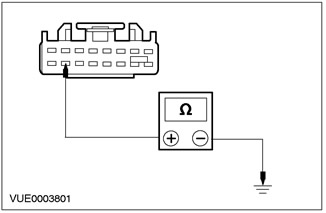
1 Measure the resistance between pin 2 of connector C897, hood switch, circuit 31-GL7 (black and yellow), from the wiring side, and "ground". |
|
• Is the resistance less than 5 ohms? |
|
|
→ Yes |
|
|
REPAIR circuit 31S-GL7 (black and yellow). CHECK the system is working properly. |
|
|
→ No |
|
|
REPAIR Circuit 31-GL7 (black and yellow). CHECK the system is working properly. |
|
|
A9: CHECKING THE GROUND SIGNAL TO THE ANTI-THEFT ALARM HORN |
|
|
1 Disconnect the C811 anti-theft alarm horn. |
|
|
2 Measure the resistance between the anti-theft alarm system connector pin C811, circuit 29S-GL26 (orange green), from the wiring side, and "ground". |
|
• Is the voltage greater than 10 V? |
|
|
→ Yes |
|
|
CLEAN and TIGHTEN the anti-theft alarm horn support mount. CHECK the system is working properly. If the problem persists, INSTALL a new theft alarm horn. CHECK the system is working properly. |
|
|
→ No |
|
|
REPAIR circuit 29S-GL26 (orange-blue). CHECK the system is working properly. |
|
|
A10: 29S-GL26 ELECTRICAL CIRCUIT CHECK (ORANGE GREEN) FOR A BREAK |
|
|
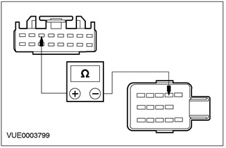
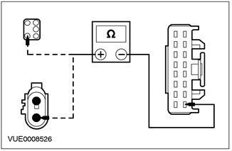
1 Measure the resistance between pin 1 of horn connector C811, circuit 29S-GL26 (orange green), on the wiring side, and pin 8 of the C452 CSM connector, on the wiring harness side. |
|
|
• Is the resistance less than 5 ohms? |
|
|
→ Yes |
|
|
RECOVER DTCs. If there are no DTCs, CHECK the system is operating correctly. If the problem persists, INSTALL a new CSM. CHECK the system is working properly. |
|
|
→ No |
|
|
REPAIR circuit 29S-GL26 (orange-blue). CHECK the system is working properly. |
|
|
A11: CHECKING THE FUNCTION OF THE HAZARD LIGHTS |
|
|
1 Operate the hazard warning lights with the hazard warning light switch. |
|
|
• Do the hazard warning lights work? |
|
|
→ Yes |
|
|
Go to A12 |
|
|
→ No |
|
|
See Section 417-01 for more information. |
|
|
A12: 31S-LG8 ELECTRICAL CIRCUIT CHECK (BLACK AND ORANGE) FOR A BREAK |
|
|
1 Enter the OFF position. |
|
|
2 Disconnect C452 CSM. |
|
|
3 Disconnect the C458 hazard warning light switch. |
|
|
4 Measure the resistance between pin 6 of connector C452 CSM, circuit 31S-LG8 (black-orange), on the wiring side, and pin 5 of connector C458 of the hazard warning light switch, on the wiring side. |
|
• Is the resistance less than 5 ohms? |
|
|
→ Yes |
|
|
INSTALL a new CSM connector. CHECK the system is working properly. |
|
|
→ No |
|
|
REPAIR circuit 31S-LG8 (black and orange). CHECK the system is working properly. |
|
|
A13: CHECKING THE FUNCTION OF THE DOOR LOCKS |
|
|
1 Operate the door locks with the key in the driver's door and in the passenger's door. |
|
|
• Do the locks lock and unlock correctly? |
|
|
→ Yes |
|
|
Go to A14 |
|
|
→ No |
|
|
See Section 501-14 for more information. |
|
|
A14: SIGNAL TEST FROM DOOR LOCK TO CSM |
|
|
1 Disconnect C452 CSM. |
|
|
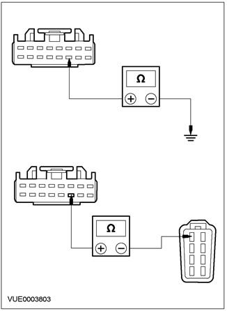
2 Measure the resistance between pin 11 of connector C452 CSM, circuit 31S-AA61B (from the driver's side) or 31S-AA61A (passenger side) (black and blue), from the wiring side, and "ground". Take readings while locking the driver's door and while locking the passenger's door. |
|
• Is the resistance less than 5 ohms when each door is locked? |
|
|
→ Yes |
|
|
Go to A16 |
|
|
→ No |
|
|
Go to A15 |
|
|
A15: DOOR UNLOCK SIGNAL TEST TO CSM |
|
|
1 Measure the resistance between pin 15 of connector C452 CSM, circuit 31S-AA62B (from the driver's side), 31S-AA62A (passenger side) (black and white), from the wiring side, and "ground". Take readings while unlocking the driver's door and while unlocking the passenger's door. |
|
• Is the resistance less than 5 ohms? |
|
|
→ Yes |
|
|
CONNECT electrical connectors and components. CHECK the system is working properly. If the problem persists, INSTALL a new CSM. CHECK the system is working properly. |
|
|
→ No |
|
|
Go to A17 |
|
|
A16: DOOR LOCK SIGNAL CHECK |
|
|
1 Disconnect the Inoperative door lock. |
|
|
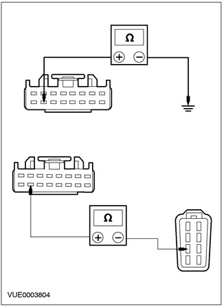
2 Measure the resistance between pin 11 of connector C452 CSM, circuit 31S-AA61A (from the driver's side), 31S-AA61 (passenger side) (black and blue), on the wiring side, and pin 5 of the inoperative door lock, electrical circuit 31S-AA61 (black and blue), from the side of the electrical wiring. |
|
|
3 Measure the resistance between pin 11 of connector C451b CSM, circuit 31S-AA61A (from the driver's side), 31S-AA61 (passenger side) (black and blue), from the wiring side, and "ground". |
|
• Is the resistance in all cases less than 5 ohms between connectors and more than 10,000 ohms to ground? |
|
|
→ Yes |
|
|
INSTALL a new door lock. See Section 501-14 for more information. CHECK the system is working properly. |
|
|
→ No |
|
|
REPAIR the electrical circuit. CHECK the system is working properly. |
|
|
A17: CHECK THE UNLOCK ELECTRICAL CIRCUIT TO THE MOTOR |
|
|
1 Disconnect the Inoperative door lock. |
|
|
2 Measure the resistance between pin 15 of connector C452 CSM, circuit 31S-AA62B (from the driver's side), 31S-AA62A (passenger side) (black and white), on the wiring side, and pin 7 of the inoperative door lock, electrical circuit 31S-AA62 (black and white), from the side of the electrical wiring. |
|
|
3 Measure the resistance between pin 15 of connector C452 CSM, circuit 31S-AA62A (driver's side, 31S-AA62 (passenger side) (black and white), from the wiring side, and "ground". |
|
• Is the resistance in all cases less than 5 ohms between connectors and more than 10,000 ohms to ground? |
|
|
→ Yes |
|
|
INSTALL a new door lock. See Section 501-14 for more information. Check the correct operation of the system. |
|
|
→ No |
|
|
REPAIR the electrical circuit. CHECK the system is working properly. |
|
|
A18: INTERIOR LIGHTING CHECK |
|
|
1 Set the interior lamp switch to the 12 SEC position. Check if the interior lighting system works correctly from the door being checked. |
|
|
• Is the interior lighting system functioning properly? |
|
|
→ Yes |
|
|
REPAIR circuit 31S-GL8 (black and yellow) (from the driver's side), for other doors: 31S-GL5B (black and blue) and for tailgate/tailgate: 31S-GL20. CHECK the system is working properly. |
|
|
→ No |
|
|
See Section 417-02 for more information. |
|
|
A19: CHECK THE ANTI-THEFT SWITCH FUNCTION |
|
|
1 Disconnect the C632 tailgate anti-theft lock switch. |
|
|
2 Measure the resistance between C800 pin 2 or C632 pin 1 (for "universal") tailgate/tailgate anti-theft alarm switch, circuit 31-GL27 (black), from the wiring side, and "ground". |
|
• Is the resistance less than 5 ohms? |
|
|
→ Yes |
|
|
Go to A20 |
|
|
→ No |
|
|
REPAIR Circuit 31-GL27 (black). CHECK the system is working properly. |
|
|
A20: TAIL DOOR/LOAD LID LOCK SWITCH TEST |
|
|
1 Measure the resistance between C800 pins 2 and 3 of the tailgate/trunk lid anti-theft alarm switch, or C632 pins 1 and 2 (for "universal"), from the side of the element. Take readings while the key is unlocking the tailgate/trunk lid and after removing the key from the lock cylinder. |
|
• Is the resistance less than 5 ohms during tailgate/tailgate key unlocking and more than 10,000 ohms otherwise? |
|
|
→ Yes |
|
|
Go to A21 |
|
|
→ No |
|
|
INSTALL a new tailgate/tailgate anti-theft lock switch. CHECK the system is working properly. |
|
|
A21: 31S-GL27 ELECTRICAL CIRCUIT CHECK (BLACK AND ORANGE) FOR A BREAK |
|
|
1 Measure the resistance between C800 pin 2 or C632 pin 2 (for "universal"), on the wiring side, and pin 1 of connector C452 CSM, on the wiring side. |
|
• Is the resistance less than 5 ohms? |
|
|
→ Yes |
|
|
CALL DTCs. If there are no DTCs, CHECK the system is operating correctly. If the problem persists, INSTALL a new CSM. CHECK the system is working properly. |
|
|
→ No |
|
|
REPAIR circuit 31S-GL27 (black and orange). CHECK the system is working properly. |
|
|
A22: CHECKING THE INTERIOR LIGHTS ARE ON FROM THE BACK DOOR |
|
|
1 Set the interior lamp switch to the 12 SEC position. Operate the interior lamps by opening the tailgate/trunk lid |
|
|
• Are the interior lights working properly? |
|
|
→ Yes |
|
|
REPAIR circuit 31S-GL20 (black and red). CHECK the system is working properly. |
|
|
→ No |
|
|
See Section 417-02 for more information. |
|
Active anti-theft system — Pinpoint tests
PINPOINT TEST A: ANTI-THEFT ALARM SYSTEM MALFUNCTIONAL
This article is available at russian, bulgarian, belarusian, ukrainian, serbian, croatian, romanian, polish, slovak, hungarian
Next articles »
Passive anti-theft system
Passive anti-theft system — diagnostics and checks
Passive Anti-Theft System — Pinpoint Tests
Transceiver for passive anti-theft system
Telematics — description and principle of operation
Telematics — diagnostics and checks
Telematics — Pinpoint tests
World Positioning System (GPS) Antenna
World System for Mobile Communications (GSM) Antenna
Cell phone — description and principle of operation
See other similar articles for Ford cars:
• General information about the anti-theft alarm system Ford Mondeo 1 and 2 (1993-2000)
• Car anti-theft system Ford Escort 5 (1990-1997)
• Anti-lock braking system (ABS), BTCS and EBD Ford Fiesta 4 (1996-1999)
• Fuel system diagnostics Ford Taurus 1 and 2 (1986-1994)
• Scheme 12. Anti-theft system Ford Fusion (2002-2012)
Link to this page in different formats
HTMLTextBB Code
No comments yet
Focus 2
Focus Turnier 1
Focus 1
- General information
- Vehicle device
- Owner's manual
- Faults en route
- Maintenance
- First maintenance
- Second maintenance
- Applications
- Consumables and spare parts
- Auto mechanic tips
- Power unit
- Engine repair
- Engine seal parts
- Cooling system
- Exhaust system
- Supply system
- Clutch
- Car gearbox
- Front wheel drives
- Chassis
- Front suspension
- Rear suspension
- Steering
- Brake system
- Wheels and tires
- Body and coating
- Body elements
- Side doors
- Tailgate
- Salon elements
- Safety system
- Windshield wipers and washers
- Body Care
- Electrical equipment
- Instruments and motors
- Battery and alternator
- Egnition lock
- Engine management
- Headlights and lighting
- Switches and sensors
- Schematic diagrams
Focus Turnier 1
- General information
- Introduction to guide
- Car care
- Power unit
- Engine repair
- Lubrication system
- Cooling system
- Fuel injection (gasoline)
- Fuel injection (diesel)
- Ignition system
- Power and exhaust system
- Transmission
- Clutch and drive shafts
- Mechanical gearbox
- Automatic gearbox
- Chassis
- Car suspension
- Steering
- Wheels and tires
- Brake system
- Body
- Exterior
- Interior
- Heating and ventilation
- Electrical equipment
- Equipment and devices
- Lighting and signaling
- Power devices
- Electrical circuits
Focus 1
- General information
- Using the manual
- Identification codes
- Power unit
- Engine
- Engine 1.4/1.6 Zetec-SE
- Engine 1.6/1.8/2.0 Zetec-E
- Engine Duratec ST 2.0 l
- Engine Duratec 8V 1.6 l
- Diesel engine 1.8 l
- Engine cooling
- Fuel supply
- Accessory drive
- Launch system
- Ignition system
- Air and vapor
- Engine management
- Exhaust toxicity
- Exhaust system
- Automatic gearbox
- Clutch
- Mechanical gearbox iB5
- Mechanical gearbox MTX-75
- Mechanical gearbox MT285
- Chassis
- Front suspension
- Rear suspension
- Wheels and tires
- Front axle axles
- Brake system
- Hydraulic brake
- Anti-lock braking system
- Steering
- Body and coating
- Body panels
- Body elements
- Salon elements
- Glass, frames and mechanisms
- Windshield wipers and washers
- Car sunroof
- Seat belts
- Body repairs
- Back elements
- Electrical equipment
- Climate control
- Heating and ventilation
- Instruments and control lamps
- Battery and alternator
- Audio system
- Headlights and lighting
- Power distribution
- Electronic Function Group
FordBook.ru © 2014-2024 • Mobile version • Interesting to read • Sitemap: EN BG BY UA RS HR RO PL SK HU • Site search • Contact with administration
Focus 1 • Focus Turnier 1 • Focus 2 • Mondeo 1 • Mondeo 1 and 2 • Mondeo 2 • Mondeo 3 • Mondeo 4 • Escort 3 • Escort 4 • Escort 5 • Fiesta 2 • Fiesta 4 • Taurus 1 and 2 • Fusion • Scorpio 1 • Scorpio 2 • Sierra •
Focus 1 • Focus Turnier 1 • Focus 2 • Mondeo 1 • Mondeo 1 and 2 • Mondeo 2 • Mondeo 3 • Mondeo 4 • Escort 3 • Escort 4 • Escort 5 • Fiesta 2 • Fiesta 4 • Taurus 1 and 2 • Fusion • Scorpio 1 • Scorpio 2 • Sierra •
Visitor comments