Crank mechanism
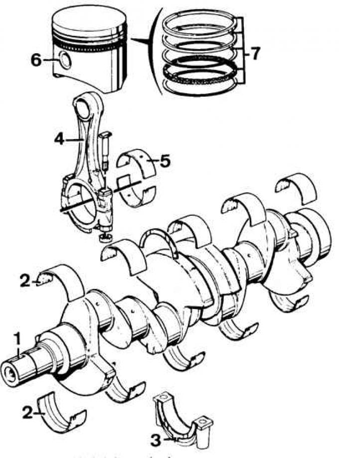
1 - crankshaft, 2 - main bearings, 3 - main bearing cap, 4 - connecting rod, 5 - connecting rod bearing, 6 - piston, 7 - piston rings
Gas distribution system
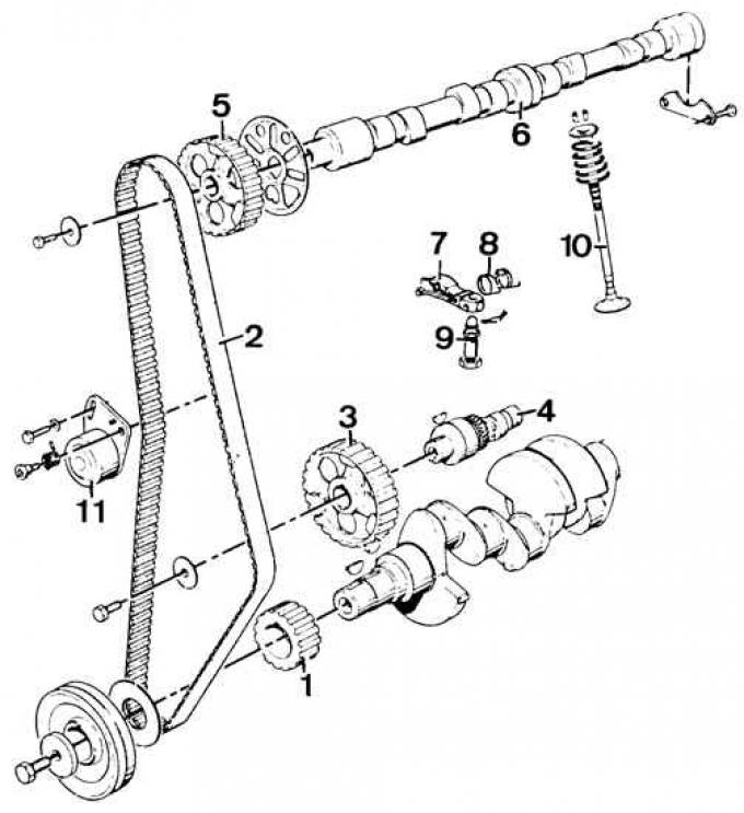
1 - crankshaft pulley, 2 - toothed belt, 3 - countershaft pulley, 4 - countershaft, 5 - camshaft pulley, 6 - camshaft, 7 - valve lever, 8 - valve lever spring, 9 - ball bolt (valve lever support), 10 - valve, 11 - toothed belt tensioner
1. Install in the hole in the back of the crankshaft (tool 21.044) clutch shaft bearing.
2. Insert the dry half-shells of the main bearings into the seats in the cylinder block.
3. Lubricate the working surfaces of the half-liners with oil and install the crankshaft on them.
4. Install the main bearing caps together with the oil-lubricated half shells (see fig. Crank mechanism - the arrows on the main bearing caps must point towards the pulley on the crankshaft).
5. Tighten the main bearing cap bolts to the correct torque and measure the crankshaft end play.
6. Install a new crankshaft rear O-ring using tool 21.011 A.
7. Coat the groove of the rear crankshaft seal cover with sealing paste (No. A 70 SX-19554-BA) and install the two halves of the gasket with a screwdriver with a blunt blade; the red gasket designation must point towards the bearing cap.
8. Install the front cylinder block cover with a new gasket.
9. Install new front o-ring (fixture 21.009 A).
10. Attach the intermediate shaft and its thrust bearing to the cylinder block; install the cover with a new sealing ring.
11.Install the flywheel on the crankshaft, tightening the bolts (oil the thread) fastening the flywheel with the appropriate torque.
12. Using special tool 21.044, center the clutch disc on the flywheel and install the clutch drive.
13. Lubricate cylinders and pistons with piston rings properly fitted.
14. Install the piston-connecting rod assembly in the cylinders, compressing the piston rings with a special tool. Point the arrows on the pistons towards the gas distribution system (see fig. Gas distribution system).
15. Install the connecting rod bearings and connecting rod caps, tightening the bolts to the correct torque. Check the end play of the connecting rods on the crankpins.
16. Install the oil pump drive shaft and screw the oil pump together with the oil supply pipes.
Attention! If a new pump is installed, fill it with oil and turn its drive shaft several times by hand.
17. Install new gaskets (lubricated with sealing paste) into the grooves of the main bearing caps of the crankshaft (back and front), insert new oil pan gaskets and press them into the grooves.
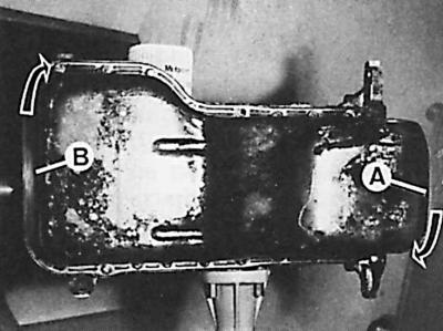
18. Install the oil pan and tighten its bolts in three stages, starting with the bolt (A), in the direction of the bolt (IN), and then from the bolt (IN) to the bolt (A).
19. Install the fuel pump drive tappet and fuel pump with gasket.
20. Install an oil sump (fix it with Loctite glue).
21. Install the coolant pump.
22. Install the oil filter with gasket. The oil filter housing should be tightened by hand until it touches and then another 3/4 turn.
23. Screw in the oil pressure sensor.
24. Install the pulley on the crankshaft (reinforced side towards flywheel).
25. Screw into the cylinder block in place of bolts No. 7 and 9 (see fig. Tightening order for cylinder head bolts), pins centering the cylinder head (see subsection 4.1.5.4). Install the cylinder head gasket with the lettering facing up.
26. Install the piston in the 1st cylinder at top dead center (TDC) and the camshaft pulley so as to get the alignment of the installation marks (see fig. Installing signs of the gas distribution system).
27. Install the cylinder head, insert (except for bolts No. 7 and 9 - see fig. Tightening order for cylinder head bolts) and lightly tighten the head bolts, remove the bolted centering pins and screw in the remaining two bolts in their place. Tighten the cylinder head bolts accordingly (see subsection 4.2.1.5).
28. Install the pulley on the crankshaft (concave side out), toothed belt and its casing (see subsection 4.1.5.4).
29. Install the elastic pipes of the cooling system and adjust the tension of the toothed belt.
Attention! From now on, the crankshaft should only be rotated in the direction of its rotation while the engine is running.
30. Adjust the position of the generator, install the coolant pump and fan.
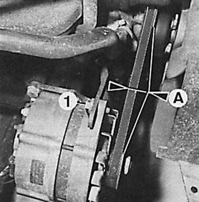
31. Install the alternator pulley and tighten the V-belt so that its deflection is 10 mm (A) (1 - tensioner bolt).
32. Check whether the piston of the 1st cylinder is installed in the TDC position, and install the ignition distributor.
33. Connect the vacuum line to the ignition system.
34. Check and, if necessary, adjust the valve clearance.
35. Install the cylinder head cover, paying attention to the correct position of its gasket.
36. Tighten the cylinder head cover bolts in the correct sequence (see fig.Tightening order for cylinder head cover bolts).
37. Screw the spark plugs into the cylinder head and connect the high voltage wires.
38. Insert a new gasket and screw the drain plug into the oil pan.
39. Connect the crankcase breather hose.
40. Insert the oil level indicator into the guide hole in the engine block.
Visitor comments