Timing drive
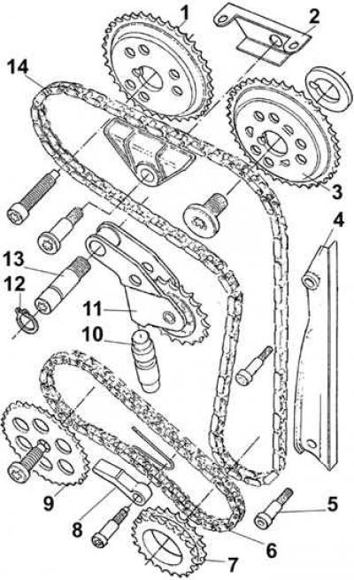
1 - Intake camshaft sprocket, 2 - Upper chain guide, 3 - Exhaust camshaft sprocket, 4 - Side chain guide, 5 - Side chain guide mounting bolt, 6 - Oil pump drive chain, 7 - Drive sprocket, 8 - Oil pump drive chain tensioner, 9 - Oil pump sprocket, 10 - Chain tensioner hydraulic tappet, 11 - Timing chain tensioner, 12 - Snap ring, 13 - Chain tensioner axle bolt, 14 - Timing chain
Gas distribution mechanism
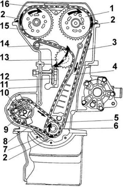
1 - camshaft sprocket controlling the exhaust valves, 2 - copper mounting elements on the side surface of the chain, 3 - timing chain, 4 - side chain guide, 6 - drive sprocket, 5 - crankshaft, 7 - oil pump drive chain tensioner, 8 - oil pump drive chain, 9 - oil pump rotor, 10 - pressure reducing valve, 11 - oil supply channel to the hydraulic tappet of the chain tensioner, 12 - hydraulic tappet of the chain tensioner, 13 - chain tensioner sprocket, 14 - chain tensioner lever, 15 - camshaft sprocket controlling the intake valves, 16 - upper chain guide
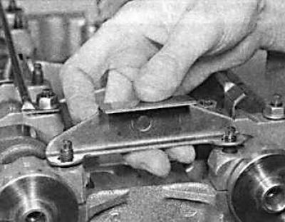
Removal the DOHC Engine Timing Chain Tensioner Shaft
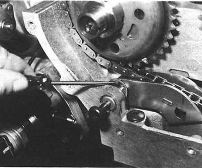
The top picture shows the removal of the retaining ring.
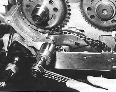
The bottom picture shows the removal of the tensioner axle.
Location of the hydraulic tappet of the tensioner of the drive chain of the DOHC engine timing system
1 – hydraulic pusher
Installing the valve timing of a DOHC engine
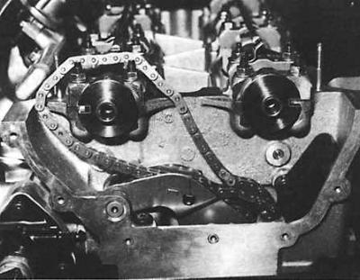
Upper figure - the installation grooves of the camshafts must be directed in different directions.
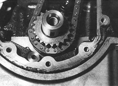
The lower figure shows the crankshaft sprocket timing marks and the copper-plated link of the drive chain.
Removal
1. Remove the ground wire from the battery.
2. Remove the V-belt from the generator and coolant pump drive.
3. Remove the air filter.
4. On vehicles with fuel injection, remove the air duct connecting the air filter to the throttle body.
5. Remove the high-voltage wires from the spark plugs and unscrew the spark plugs.
6. Remove the distributor cap together with the high-voltage wires.
7. Disconnect the engine crankcase ventilation hose from the cylinder head cover breather.
8. Disconnect the accelerator pedal cable. In a carburetor engine, unscrew the throttle cable together with the holder, and in a fuel-injected engine, disconnect the rod from the throttle body after removing it from the side of the clamp made of artificial material.
9. Remove the cylinder head cover.
10. Remove the ignition distributor.
11. Remove the upper timing cover.
12. Turn the crankshaft in the direction of working rotation until it reaches the top dead center in the compression stroke of the piston of cylinder 1.
Caution! The crankshaft can be turned with a spanner by the middle bolt of the sprocket in the direction of its working rotation until the marks on the camshaft sprockets are at the height of the upper plane of the cylinder head and are directed outward in both camshafts.
13. Loosen the crankshaft pulley mounting bolt. To prevent the crankshaft from turning when unscrewing the pulley, secure the flywheel by the teeth of the ring gear or engage fifth gear and have an assistant press the foot brake all the way down.
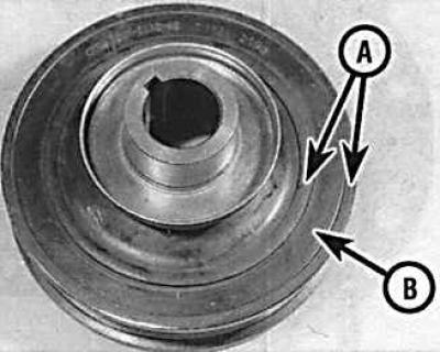
14. Partially unscrew the crankshaft pulley mounting bolt and remove the pulley using a puller. The puller jaws should rest against the metal part of the pulley (A - locations of the puller jaws on the pulley). Do not place the puller jaws on the rubber surface (B).
15. Unscrew the long lower generator mounting bolt, then the upper bolt and remove the generator.
16. Unscrew the central bolt securing the drive belt tensioner mechanism and remove the tensioner mechanism.
17. Unscrew 11 mounting bolts and remove the lower timing cover. Remove the rubber seal.
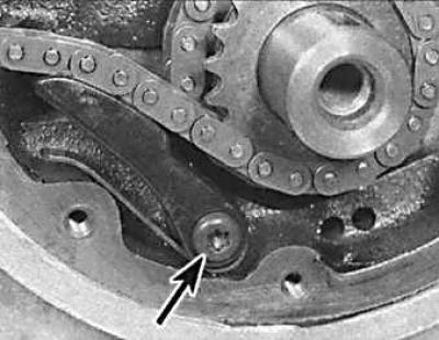
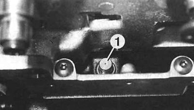
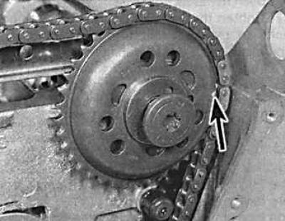
18. Unscrew the bolt (indicated by the arrow) and remove the oil pump drive chain tensioner.
19. Unscrew the bolt securing the sprocket to the oil pump and remove the sprocket together with the chain.
20. Remove the upper chain guide.
21. Unscrew the two bolts securing the lower chain guide and remove it upwards.
22. Remove the retaining ring from the timing chain tensioner lever shaft and remove the tensioner lever.
23. Remove the timing chain tensioner lever axle using an M6x70 bolt and bushing.
24. Mark the camshaft sprockets and remove them.
25. Remove the sprocket and woodruff key from the crankshaft.
26. Remove the timing chain upwards.
Caution! To avoid collision of pistons and valves, do not turn the engine crankshaft when the timing chain is removed.
27. Remove the chain tensioner.
28. Remove the hydraulic chain tensioner plunger.
29. Disassemble the hydraulic chain tensioner plunger and drain the oil from it.
30. Pour fresh engine oil into the hydraulic pusher housing of the chain tensioner, and using special device 21-145 assemble the chain tensioner as follows. Install the pusher housing with the hole facing up. Install the device on the pusher housing, and the conical part of the device should be directed upwards. Install the pusher plunger on the device and compress the assembly until a slight click, while the pusher should be fixed in the lower position.
Examination
Check the timing chain, sprockets and chain tensioner for wear and damage. If the plastic sprocket of the chain tensioner is worn, the entire tensioner unit must be replaced, since the sprockets are not supplied separately.
Hydraulic chain tensioner pusher
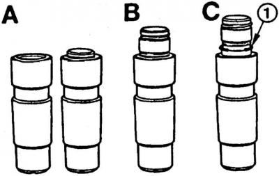
A – normal position of the plunger,
B and C – strong piston protrusion (the plunger must be replaced),
1 – retaining ring
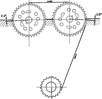
Position of the sprocket installation marks corresponding to the installation of the piston of cylinder 1 at the top dead center in the compression stroke
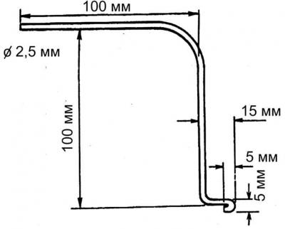
Special tool made from 2.5mm diameter wire to release the chain tensioner pusher plunger
Please note: The timing chain contains copper elements that are used to correctly position the timing mechanism when installing the chain.
Installation
1. Check that the crankshaft is in the position corresponding to the installation of the piston of cylinder 1 at the top dead center in the compression stroke, while the keyway should be directed downwards.
2. Lower the chain from the top into the casing, with the single copper link of the chain at the bottom.
3. Insert the key into the crankshaft groove.
4. Install the chain on the inner (large) sprocket, aligning the copper link of the chain with the mark on the sprocket.
5. Install the sprocket on the crankshaft, aligning the groove on the sprocket with the key, while the mark on the sprocket should be strictly at the bottom.
6. Insert the lower chain guide into place from above and screw it on with bolts whose threads are coated with a material that prevents the bolts from loosening.
7. Install the hydraulic chain tensioner plunger. The plunger plunger should be level with the housing or protrude slightly from it. If the plunger protrudes significantly or the retaining ring on the plunger is visible, the hydraulic chain tensioner plunger must be replaced.
8. Install the chain tensioner lever, tensioner lever shaft and secure it with a lock washer.
9. Check and, if necessary, reset the camshafts. The camshafts must be in a position corresponding to the installation of the piston of cylinder 1 at the top dead center in the compression stroke, and the installation protrusions for the sprockets must be in line with the upper edge of the cylinder head and directed outward.
10. Install the chain onto the exhaust camshaft sprocket, aligning the mark on the sprocket with the middle of the section of chain between the copper links of the chain.
11. Install the sprocket on the camshaft. The mark on the sprocket (indicated by the arrow) should be in line with the top edge of the cylinder head and facing outward.
12. Screw on the sprocket mounting bolt.
13. Install the chain onto the intake camshaft sprocket, aligning the mark on the sprocket with the middle of the section of chain between the copper links of the chain.
14. Install the sprocket onto the camshaft.
Caution! When installing the sprockets, the drive chain must be tensioned on the opposite side of the tensioner. The mark on the sprocket must be in line with the top edge of the cylinder head and facing outward.
15. Install the upper timing chain guide.
16. Turn the crankshaft several revolutions in the direction of engine operating rotation.
17. Check the position of the hydraulic tappet plunger. If the tappet plunger protrudes significantly from the housing, press it in by pressing the chain tensioner lever. If the tappet plunger is below the level of the upper edge of the tappet housing, a special tool made of 2.5 mm diameter wire must be used to release the plunger.
18. Carefully pry the tensioner lever, then insert a tool between the lever and the plunger. Remove the screwdriver and release the plunger by pressing the chain tensioner lever and remove the tool.
19. Turn the crankshaft two revolutions in the direction of engine operating rotation and check the marks on the camshaft sprockets, which should be in line with the upper edge of the cylinder head and facing outward.
20. Turn the crankshaft one revolution in the direction of engine rotation and check the marks on the camshaft sprockets, which should be in line with the upper edge of the cylinder head and facing each other.
21. Install the oil pump drive chain onto the crankshaft sprocket, then install the drive sprocket and chain onto the oil pump.
22. Install the oil pump chain tensioner.
23. Check the condition of the sealing ring in the upper timing cover. If necessary, remove the old sealing ring and use a tubular mandrel to install a new ring with the working edges facing the engine.
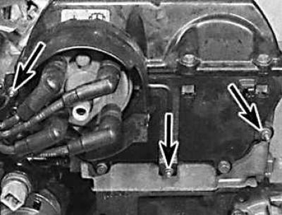
24. Install the top cover of the timing mechanism with a new gasket (the fastening nuts are indicated by arrows).
25. Install the cylinder head cover.
26. Check the condition of the sealing ring in the lower timing cover. If necessary, remove the old sealing ring and, using a tubular mandrel, install a new ring with the working edges facing the engine.
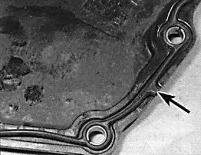
27. Install the lower timing cover with a new gasket, without tightening the mounting bolts. The protrusion (indicated by the arrow) on the gasket should enter the groove of the lower cover.
28. Install the auxiliary belt pulley onto the crankshaft and secure it with the old bolt, while centering the lower timing cover and finally tightening the cover mounting bolts.
29. Unscrew the old bolt from the pulley and screw in a new one, tightening it to the required torque.
30. Install the auxiliary belt tensioner mechanism, making sure that the protrusion on the rear of the tensioner mechanism fits into the corresponding hole in the engine cylinder block.
31. Install the generator.
32. Further assembly is carried out in the reverse order of disassembly.
[For more information, please visit the specified website: Fordbook.ru]