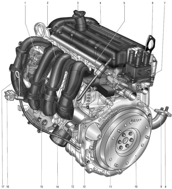
Fig. 5.1. Engine: 1 – generator; 2 – intake module; 3 – oil filler cap; 4 – cylinder head cover; 5 – fuel rail; 6 – ignition coil; 7 – coolant temperature sensor; 8 – cylinder head; 9 – cat collector; 10 – flywheel; 11 – cylinder block; 12 – starter; 13 – oil pan; 14 – oil filter; 15 – air conditioning compressor; 16 – Engine cooling system fan wiring harness connector; 17 – oil level indicator (dipstick)
The Duratec 1.6 engine (Fig. 5.1) with an overhead arrangement of two five-bearing camshafts has four valves per cylinder. The camshafts are driven by a reinforced toothed belt. The belt tension is provided by a tension roller spring. The valves are driven directly from the camshafts through cylindrical tappets, which also serve as adjusting elements for clearances in the drive.
IN cylinder head, made of aluminum alloy according to the transverse scheme of cylinder scavenging (inlet and outlet channels are located on opposite sides of the head), seats and valve guides are pressed in. The inlet and outlet valves have one spring each, fixed through a plate with two crackers. The cylinder head is centered on the block with two bushings and attached with ten screws. A shrink-resistant metal-reinforced gasket is installed between the block and the head. In the upper part of the cylinder head, there are five bearing supports for the plain bearings of the two camshafts. The lower parts of the supports are made in one piece with the cylinder head, and the upper ones (covers) are attached to the head with screws. The holes in the supports are machined together with the covers, so the covers are not interchangeable and each of them has a serial number.
Cylinder block the block is a single casting made of special high-strength cast iron, forming the cylinders, cooling jacket, upper part of the crankcase and five crankshaft supports, made in the form of crankcase partitions. The cylinders are bored directly in the block body. In the lower part of the block there are five main bearing beds with removable covers attached to the block with bolts. The main bearing covers are machined together with the block and are not interchangeable. In the bearing beds (in the upper parts of the supports) there are outlet openings of oil channels intended for lubrication of the main bearings, as well as through holes into which ball valves with nozzles are pressed, through which oil is sprayed onto the piston bottoms and cylinder walls. On the cylinder block there are special bosses, flanges and openings for fastening parts, units and assemblies, as well as channels of the main oil line.
Crankshaft, made of high-strength cast iron, rotates in main bearings equipped with thin-walled steel liners with an antifriction layer. The upper liners, installed in the cylinder block, have a groove on the inner surface and a through slot through which oil flows from the outlet of the oil channel to the ball valve with a nozzle. The lower liners do not have grooves and slots. The axial movement of the crankshaft is limited by two identical thrust half rings. A flywheel is attached to the rear end of the crankshaft with six bolts. A toothed pulley of the timing mechanism drive and a pulley of the auxiliary units drive are installed on the front end of the crankshaft.
Pistons with a short skirt are made of aluminum alloy. On the cylindrical surface of the piston head there are ring grooves for two compression rings and an oil scraper ring. The groove of the oil scraper ring has six holes for draining the oil removed by the ring from the cylinder walls. Oil is supplied to the piston pin through two of these holes.
Piston pins tubular section are installed in the piston bosses with a gap and pressed with tension into the upper heads of the connecting rods, which are connected by their lower heads to the connecting rod journals of the crankshaft through thin-walled liners, the design of which is similar to the main liners.
Connecting rods steel, forged, with an I-section rod. The connecting rods are machined together with the caps. In order not to mix them up during assembly, the cylinder ordinal number is applied to the side surfaces of the connecting rods and caps.
Camshafts cast, iron.
The gas distribution mechanism is covered by a plastic cylinder head cover. It contains an oil separator for the crankcase ventilation system.
Lubrication system combined (for more details see. "Lubrication system").
The oil pan, cast from aluminum alloy, is attached to the bottom of the cylinder block. The oil pan flange is sealed with WSE-M4G323-A4 sealant gasket. The pan has a hole with a threaded plug for draining the oil.
Oil filter full-flow, non-separable, with bypass and anti-drain valves.
Crankcase ventilation system closed, forced, with crankcase gases being removed through an oil separator into the air filter cavity.
Cooling system engine is sealed, with an expansion tank (for more details see. "Cooling system").
Engine power supply system consists of an electric fuel pump installed in the fuel tank, a throttle assembly, a fine fuel filter and a fuel pressure regulator installed in the fuel pump module, a fuel pressure pulsation compensator, injectors and fuel lines, and also includes an air filter.
Ignition system microprocessor, consists of an ignition coil, high-voltage wires and spark plugs. The ignition coil is controlled by an electronic engine management system unit. The ignition system does not require maintenance or adjustment during operation.
Power unit (engine with gearbox, clutch and final drive) is mounted on three supports with elastic rubber elements: two front ones, which support the main weight of the power unit, and a rear one, which compensates for the torque from the transmission and the loads that occur when the car starts moving, accelerates and brakes.
The full article is on the online resource [FORDBOOK.RU]