Withdrawal
1. Apply the parking brake.
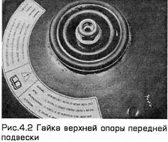
2. In the engine compartment, remove the cap from the rack (if available). While holding the strut stem with a hex wrench, loosen the top mount nut and unscrew it 5 turns (see figure 4.2). Do not unscrew it all the way yet, but note that you will need a new nut when installing.
3. Loosen the nuts of the corresponding wheel and support the rear wheels with wedges. Raise the front of the car and place it on stands. Remove the front wheel.
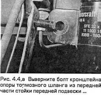
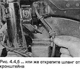
4. Remove the brake hose support bracket bolt from the front of the front suspension strut or unfasten the hose from the bracket (see fig. 4.4, a, b).
5. Remove the ABS sensor (if available - see chapter 9).
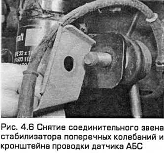
6. Turn away a nut and disconnect a connecting link of the stabilizer of cross-section fluctuations from a rack of a suspension bracket. Please note that on models with ABS, the ABS sensor wiring bracket is installed under the nut (see fig. 4.6).
7. Remove the brake caliper (chapter 9), without disconnecting the caliper hose. Tie the caliper inside the wheel arch without pulling on its hose.
8. Remove the cotter pin from the ball joint nut of the tie rod end switch. Loosen the nut and remove the linkage from the steering knuckle using a ball joint puller. Do not damage the ball joint seal.
9. Remove the clamp that secures the inner cover of the drive shaft to the inner constant velocity joint. Detach boot from hinge body.
10. Consider which side the lower arm ball joint clamp bolt is installed. Then remove the bolt from the steering knuckle. Separate ball joint (wringing it out) from a fist. If this is difficult to do, open the clamp with a pry bar or power screwdriver. Do not damage the ball joint seal.
11. Disconnect the electrical connector (in the presence of) adaptive suspension located on the suspension strut and unfasten the wiring harness.
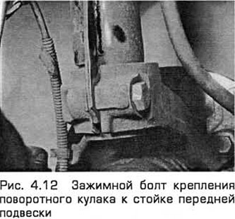
12. Turn out a tightening bolt of fastening of knot of a rotary fist to a rack of a forward suspension bracket, considering what side it is installed. Open the clamp with a pry bar or screwdriver and release the fist from the post (see fig. 4.12.).
13. Lower the suspension strut together with the drive shaft and steering knuckle. Remove the input shaft joint from the inner constant velocity joint housing.
Installation
14. Open the clip and install the suspension strut on the steering knuckle. Insert clamp bolt like this. so that his head is pointing forward. Tighten the bolt to the required torque.
15. Install suspension strut (together with the drive shaft and steering knuckle) into its top support. Screw on the nut.
16. Install the internal constant velocity joint of the input shaft into its housing. Then install the cover on the case and fix it with a new clamp.
17. Connect the electrical connector (in the presence of) adaptive suspension and fix its wiring.
19. Fully insert the ball joint pin of the lower arm into the bottom of the steering knuckle. Install the clamp bolt and tighten to the specified torque.
20. Connect the anti-roll link to the strut and tighten the nut to the specified torque. On models equipped with ABS, be sure to install the sensor wiring bracket under the nut.
21. Install the ABS sensor (in the presence of), see chapter 9.
22. Install the ball joint of the tie rod end switch on the steering knuckle and tighten the nut to the required torque. Check that the pin holes must line up. If necessary, slightly turn the nut until it is aligned, taking into account the required torque indicated in Technical requirements. Insert a new cotter pin and straighten it.
23. Install the brake caliper (chapter 9).
24. Install the brake hose support bracket on the rack and tighten its bolt.
25. Install the wheel and lower the vehicle to the ground.
26. Tighten the wheel nuts to the required torque.
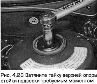
28. Tighten the suspension strut top nut to the required torque while holding the piston with an 8mm hex wrench. If you do not have the adapter required for this, then first tighten the nut with a spanner wrench while holding the piston. Then tighten the nut to the required torque using a normal socket (see fig. 4.28).
Visitor comments