Contents: Removal ↳ Installation ↳
Removal
1. Apply the parking brake. Remove the hubcap from the appropriate wheel. Loosen (but do not remove) the drive shaft/hub nut. This nut is tight.
2. Loosen the wheel mounting nuts. Raise the front end and place it on supports. Remove the front wheel.
3. Remove the cotter pin from the tie rod end ball joint nut.
4. Loosen the nut and disconnect the tie rod from the steering knuckle using a ball joint puller. Be careful not to damage the ball joint seal.
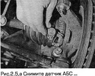
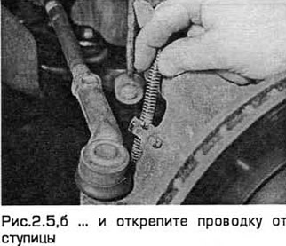
5. Remove the ABS sensor (see Fig. 2.5,a,6) (if present - see chapter 9).
6. Remove the brake caliper and brake disc (chapter 9), without disconnecting the caliper hose. Tie the caliper inside the wheel well without stretching its hose.
7. Unscrew the drive shaft/hub nut. This nut is special and after unscrewing it can be reused no more than five times. It makes sense to put a mark on the nut after unscrewing it. If necessary, buy a new nut.
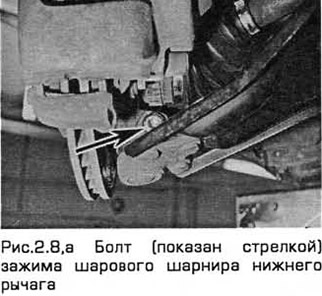
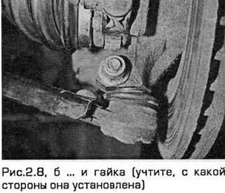
8. Note which side the lower arm ball joint clamp bolt is installed on. Then unscrew the bolt from the steering knuckle. Separate the ball joint (by pushing it) from the knuckle. If this is difficult to do, open the clamp with a crowbar or power screwdriver. Do not damage the ball joint seal (see Fig. 2.8, a, b).
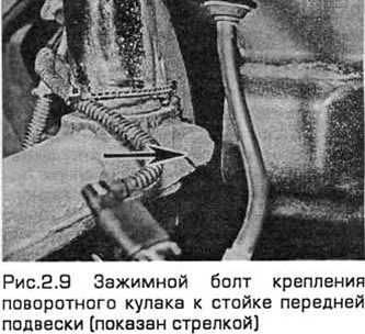
9. Unscrew the clamp bolt securing the steering knuckle to the front suspension strut, taking into account which side it is installed on (see Fig. 2.9). Open the clamp with a crowbar or screwdriver and release the knuckle from the strut. If necessary, knock the knuckle off with a soft-faced hammer. Lean the knuckle on a support.
10. Remove the knuckle and hub assembly from the drive shaft splines. If this is difficult, fit a puller to the hub flange and separate the knuckle from the drive shaft. After removing the knuckle, support the drive shaft on a stand or tie it to the wheel well so that the inner constant velocity joint does not rotate more than 18°.
Installation
11. Install the knuckle with the hub on the splines of the drive shaft and support the unit on a stand.
12. Install the unit onto the front suspension strut. Insert the clamp bolt with its head facing forward. Install and tighten the nut to the specified torque.
13. Install the lower control arm ball joint onto the knuckle assembly and insert the clamp bolt with its head facing forward. Install and tighten the nut to the specified torque.
14. Install the drive shaft/hub nut and tighten it lightly.
15. Install the brake caliper and brake disc (chapter 9).
16. Install the ABS sensor (if available - chapter 9).
17 Install the ball joint of the tie rod end onto the steering knuckle and tighten the nut to the specified torque. Check that the holes for the cotter pin are aligned. If necessary, turn the nut slightly until aligned, taking into account the required torque specified in Technical requirements. Insert a new cotter pin and bend it.
18. Install the front wheel and lower the vehicle to the ground.
19. Tighten the wheel nut to the specified torque.
20. Tighten the drive shaft/hub nut to the specified torque and install the wheel cover.
[The original post is on the web portal: FordBook.ru]