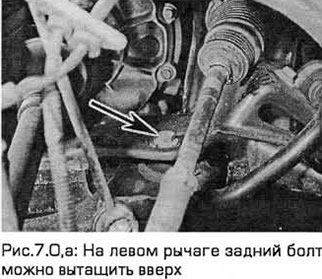
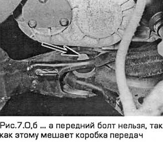
Note: On the left arm, the front bolt cannot be pulled up (see Fig. 7.0, a, b). Therefore, to remove the bolt, you need to disconnect the power unit from the supports and lift it up.
Removal
Right lower control arm
1. Apply the parking brake. Raise the front of the vehicle and place it on stands. Remove the appropriate front wheel.
2. If you are removing the lower arm on the right side, remove the accessory drive cover (where necessary).
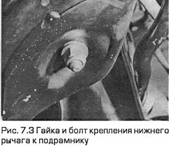
3. Unscrew the nuts and bolts securing the lower arm to the subframe (see Fig. 7.3).
4. Loosen the nuts and disconnect the connecting links from the anti-roll bar on both sides. Rotate the anti-roll bar upward, moving it away from the lower arm.
5. Remove the cotter pin from the tie rod end ball joint nut. Remove the nut and disconnect the tie rod from the steering knuckle using a ball joint puller. Be careful not to damage the ball joint seal.
6. Remove the clamp securing the inner boot of the drive shaft to the inner constant velocity joint. Disconnect the boot from the joint housing. This is necessary to avoid damaging the boot when moving the knuckle upward to remove the lower arm.
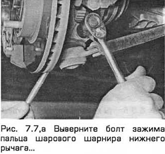
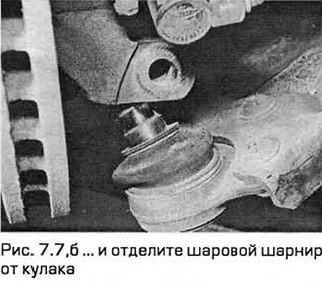
7. Note which side the lower arm ball joint pin clamp bolt is installed on. Then unscrew the bolt from the steering knuckle. Separate the ball joint (by pushing it) from the knuckle. If this is difficult to do, open the clamp with a crowbar or power screwdriver. Do not damage the ball joint seal (see Fig. 7.7, a, b).
8. Remove the lower arm from the subframe.
Left lower control arm - models with non-automatic transmission
9. In the engine compartment, remove the strut cap (if present). Holding the strut rod with an Allen key, loosen the upper support nut and unscrew it 5 turns. Do not unscrew it completely yet, but keep in mind that you will need a new nut for installation
10. Remove the air cleaner (chapter 4A).
11. Apply the parking brake, chock the rear wheels. Loosen the front wheel nuts. Raise the front of the car and place it on supports. Remove the front wheels.
12. Disconnect the shift linkage and support rods from the transmission (chapter 7A).
13. Disconnect the left drive shaft from the transmission (chapter 8). Support the inner end of the shaft against the support.
14. Unscrew the clamp bolt securing the steering knuckle to the lower arm of the front suspension, taking into account which side it is installed on. Open the clamp with a pry bar or screwdriver and release the hinge pin from the knuckle.
15. Support the power unit with a jack.
16. Remove the bolts securing the front and rear engine mounts to the subframe. Mark the position of the mounts.
17. Remove the bolts securing the right and left engine mounts to the subframe.
18. Carefully lift the power unit approximately 50 mm, being careful not to put any strain on the wires or pipes.
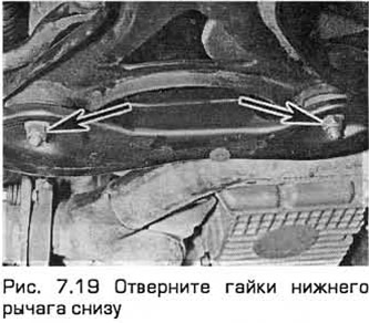
19. Unscrew the bolts and nuts securing the lower arm to the subframe. Remove the arm (see Fig. 7.19).
Left Lower Control Arm - Automatic Transmission Models
20. Disconnect the steering column shaft from the flexible coupling (paragraph 28).
21. Apply the parking brake, chock the rear wheels. Loosen the front wheel nuts. Raise the front of the car and place it on supports. Remove the front wheels.
22. Remove the exhaust pipe (chapter 4A).
23. Remove the lower radiator cover and the right and left wheel arch liners. To do this, unscrew the screws and release the clamps.
24. Disconnect the front bumper brackets and move them to the side.
25. Secure the radiator in its working position. To do this, insert cotter pins into the holes in the radiator rods that protrude from its upper supports.
26. Remove the bolts and lower radiator support brackets.
27. Remove the bolts (if any) securing the air conditioning system accumulator to the subframe. Support the accumulator to avoid straining the pipes.
28. Remove the nuts and disconnect the connecting links from the anti-roll bar on both sides. Rotate the anti-roll bar upward, moving it away from the lower arm.
29. Remove the cotter pins from the tie rod end ball joint nuts. Remove the nuts and disconnect the rods from the steering knuckles using a ball joint puller. Be careful not to damage the ball joint seals.
30. Unscrew the clamp bolts securing the steering knuckles to the lower arms of the front suspension, taking into account which side they are installed on. Open the clamps with a pry bar or screwdriver and release the hinge pins from the knuckles.
31. Disconnect the power steering radiator pipes from the subframe.
32. Remove the bolts securing the front and rear engine mounts to the subframe. Mark the position of the mounts.
33. Loosen the nuts securing the lower arms to the subframe. Both bolts can only be removed after the subframe has been lowered.
34. Mark the position of the subframe before removing and installing it.
35. Remove the rear subframe mounting bolts (silver) and loosen the front subframe mounting bolts (gold) by 2 turns. Lower the subframe to access the hydraulic steering system fittings on top of the steering gear.
36. Place a container underneath it and unscrew the nuts of the fittings on the discharge, drain and cooling pipes. Then unscrew the clamp bolts and disconnect the pipes. The liquid will drain into the container. Plug the holes.
37. Check that everything is disconnected from the subframe.
38. Remove the front subframe mounting bolts and lower the subframe so that you can remove the lower arm mounting bolts to the subframe and remove the arm.
Repair
39. Check the rubber bushings and the lower arm ball joint for wear and damage. The ball joint can be replaced (paragraph 8). The rubber bushings can be pressed out or removed using a metal pipe, a long bolt, a nut and washers.
40. Note that the front and rear bushings are different. The front has a cylindrical inner tube, and the rear has a barrel-shaped one (see Fig. 7.40).
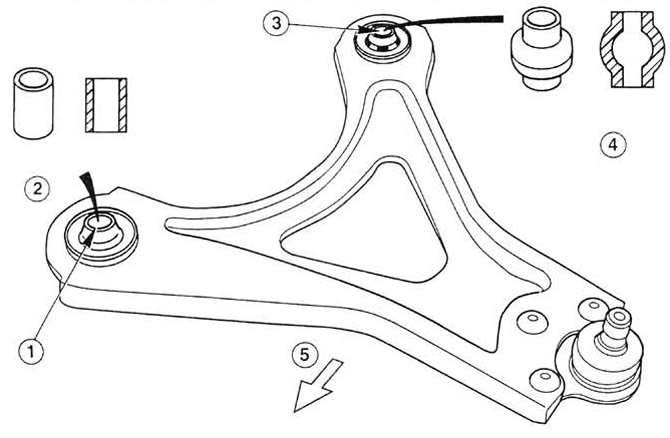 Fig. 7.40. Front suspension lower arm bushings.
1. Front hub
2. Cylindrical inner tube
3. Rear hub
4. Barrel-shaped inner tube
5. Front of the car
41. Press new bushings into the lower arm in the same way as when removing. Note that the rubber ends of the bushings must be at the same level. On the latest models, the end of the rear inner bushing must match the triangular mark on the arm.
Installation
42. Installation is in the reverse order of removal.
(The text is available on the specified website info portal: FordBook)