Introduction
The bodywork plays a significant role in the growing trend towards faster and faster model changes. Different customer groups are strongly influenced by the design and shape of the body. At the same time, body stability plays the most important role in ensuring the safety of the driver and passengers. Lightweight construction, alternative materials, composite materials, plastics and related joining processes are all design features that characterize modern Ford vehicle bodies.
With modern factory body technologies with safety cages (load-bearing bodies) can be produced almost without problems. Information about the strength characteristics, accumulated on the basis of multiple computer simulations, «crash tests» (collisions with obstacles), material testing and technology improvement analysis, ensures the high quality of Ford products. When performing repairs, be sure to adhere to all factory quality standards. This requires a well-equipped service station and emphasizes the qualifications of service station technicians. To ensure high-quality body repair, knowledge of the factory technologies used and constant training in new repair methods and technologies are essential. Model-specific repair manuals and general repair procedures provide invaluable assistance when performing body repairs.
The body structure is becoming more and more complex, changing the topics covered in the Body Repair Manual. In the future, only the most important repair procedures and techniques will be described in the general section. Extensive knowledge of the main methods and technologies for performing repairs is assumed. For example, repair actions that are repeated will be applicable to all vehicle models and will be described in a general section. Model-specific sections of body repair manuals will only show the most important repair steps or draw attention to specific features. Special training courses for new models will provide additional practical information, as well as advice and description of body repair techniques.
Load-bearing body (combined with frame)
The design with a monocoque body has firmly established itself in the automotive market.
Its main advantages are:
- Maximum safety for the driver and passengers.
- Significant weight reduction.
- Economical manufacturing technology.
The load-bearing body is complemented by separate assembly units, such as doors, hood, bumpers, etc. Once assembled, this design is particularly advantageous in terms of stability and rigidity, with:
- Stability of the passenger accommodation area.
- Accurately defined character of deformation in front and behind.
- Additional lateral stability.
- High torsional rigidity.
- High bending strength.
When carrying out repairs, the following instructions must be observed:
- Straightening work should only be carried out when the body is fully assembled.
- Do not cut pasted windows when editing.
- Avoid tension in the body.
- If possible, keep the body assembled during the repair process.
Structure with a load-bearing body
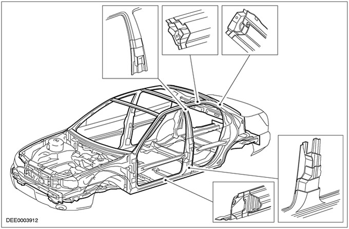
Design features with a monocoque body
For every body structure, the safety of the driver and passengers is paramount. The body has two key safety features:
- safety cage
- Collapse zones
Safety cage
The safety cage is characterized by the following design features:
- Stable pillars, door sills and door profiles.
- Built-in shock protection in the doors.
- Doors are designed to open even in case of excessive deformation.
Collapse zones
The roll cage is protected by front and rear crumple zones with well-defined deformation characteristics. Collapse zones serve the following purposes:
- Dynamic absorption of deforming forces.
- Protecting the passenger area.
Always follow the repair instructions in the workshop literature, especially when repairing a crinkled area. Failure to follow these instructions in some situations can have a serious impact on the safety of the vehicle. For example, no cuts should ever be made in the immediate vicinity of the bridge pier anchorages, nor should any stiffeners be randomly welded. After completing the work, all prescribed safety regulations must be strictly observed.
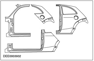
Collapse zones - Roll cage (passenger accommodation area)
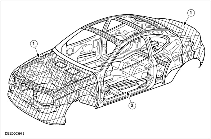
| Pos. | Spare Part No | Name |
| 1 | - | crumple zone |
| 2 | - | safety cage (passenger accommodation area) |
Off-road vehicles («SUVs»)
Body structure «SUVs» differs from the design with a load-bearing body by the presence of a 2-section body structure. The extremely stable chassis frame forms the base to which all vehicle components such as axles, engine, etc. are attached. The body itself is bolted to the chassis frame. This design has the following advantages:
- High payload and large trailer capacity.
- Excellent strength characteristics for off-road use.
- Very high ground clearance.
If «SUV» needs to be repaired, the following notes should be taken into account:
- It is well known that both frame spars should be parallel to each other.
- If necessary, before editing the chassis frame, remove the body with bolts to the frame from it.
Off-road car design
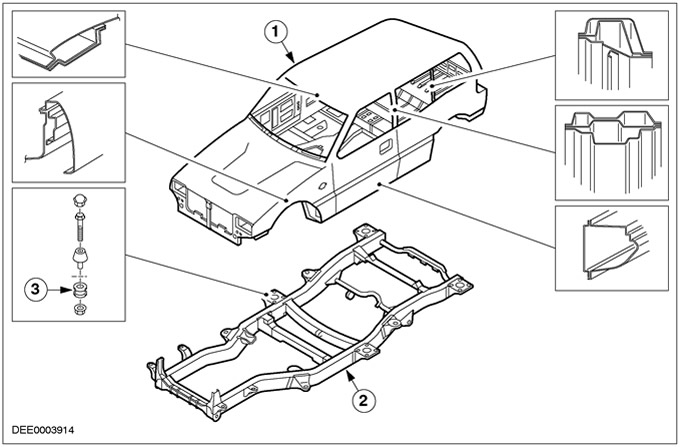
| Pos. | Spare Part No | Name |
| 1 | - | Body |
| 2 | - | Frame |
| 3 | - | Bolted connection |
High strength low alloy steel
general information
- High-strength, low-alloy steel is used in Ford vehicle bodies primarily for beams, tie plates, supports, and struts.
- Model specific chapters explain where high strength low alloy steel is used.
Specific features of high strength low alloy steel:
- Stronger tendency to retain the deformed shape.
- Editing requires more effort.
- As a result of the tendency to retain the deformed shape, any deformed elements when working on the straightening press should be well stretched beyond the original state.
- All tools used for surface metal removal (e.g. when milling spot welds), have a reduction in life expectancy due to the higher degree of hardness.
- Do not apply heat when dressing as this will cause loss of mechanical strength can already occur at a temperature of approximately 400°C.
- During the manufacturing process, hardened steel reaches its final hardness when it is placed in a painting oven.
|
Steel type |
Special properties |
Low-alloyed thin sheet metal - galvanized sheet metal - zinc - zinc-nickel |
Flame galvanized sheet metal - galvanized - galvanized with aluminum |
|
High strength low alloy steel |
Very good ductility on stamped panels with complex shapes or in areas of low stability (e.g. inner door panel or wheel arch) |
180 |
180 |
|
Hardened steel (furnace hardening) |
Good plasticity; additional surface hardness achieved in combination with heat treatment (staining) (e.g. flat elements like the outer panel of a door or bonnet). |
180, 220, 260, 300 |
180, 220, 260 |
|
Alloy steel with phosphorus content |
Good resilience on stamped elements in medium stability areas (e.g. wheel arch) |
220, 260, 300 |
220, 260, 300 |
|
low alloy steel |
High degree of rigidity for load-bearing body elements |
260, 300, 340, 380, 420, 460 |
340, 380, 420 |
|
Isotropic steel |
Good resilience in medium stability zones as a result of high tensile characteristics and isotropic deformation properties (e.g. flat elements like door outer panel, bonnet) |
220, 260 |
260, 300, 340 |
Table: Minimum tensile strength for high strength low alloy steel in N/mm2
High strength low alloy steel (example: Mondeo)
Anti-corrosion protection
Collision damage and diagnostics. General Notes:
- Accurate diagnosis of damage size ensures correct repair planning.
- Do not weld additional reinforcing plates.
- All body repairs should be carried out in accordance with the recommendations in the Body Repair Manual.
- When carrying out body repairs, the stability and strength characteristics of the body must be taken into account. The frames of load-bearing bodies have a precisely defined deformation pattern, which should not be affected by any type of repair.
- For example, crumple zones absorb a large proportion of the energy in a collision. If any non-professional repair methods or techniques are used in these areas, it may pose a safety hazard to the vehicle.
Hidden Damage
- Along with looking for external signs such as peeling paint, be sure to check for hidden body damage or deformation that is not visible from the outside. To obtain an accurate assessment of damage to hidden body parts, it is often necessary to remove large attached parts such as bumpers and inner fenders.
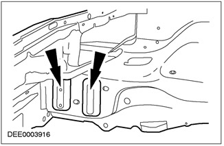
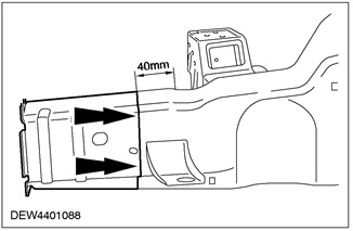
Specified places of deformation
- When evaluating damage to the bodywork, the predetermined places of deformation of the bodywork should always be checked. The given deformation places are intentional «weakened sections», created by locally changing the shape of the section, which will be the first to be exposed to external forces.
Predetermined places of deformation - by means of a special change in the shape of the body panels
Defined deformation points - through the use of different material thicknesses
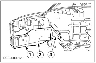
| Pos. | Spare Part No | Name |
| 1 | - | Material thickness 2.0 mm |
| 2 | - | Material thickness 3.0 mm |
| 3 | - | Material thickness 1.75 mm |
Nodal welds
- Nodal welds are key locations in the car body frame. Signs of damage, such as peeling paint in the area of the nodal welds, are often an obvious sign of significant damage. For this reason, when assessing damage, all parts of the bodywork connected by a nodal weld should be checked very carefully for any signs of damage.
The action of forces in the zone of nodal welds)
Gap size
- The size of the gaps offers another diagnostic option through visual inspection. If there are any changes or misalignment of the edges, this usually indicates that the dimensions of the problematic spare part are incorrect.
Clearance changes
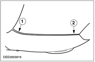
- Pos.##Spare Part##Description
- 1##-##Gap too wide
- 2##-##Gap too narrow
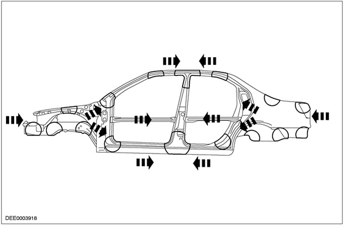
The impact of a collision on the body
NOTE: Vehicle components such as axle shafts and trailer attachments (trailer), transfer forces. If the car has been hit from behind, then all connected body elements and mechanical elements should be fully checked (e.g. gearbox mounts). Check the electronic components to make sure they are working properly.
In addition, it is possible to set the entire amount of damage, starting with the direction and magnitude of the impact forces. This however requires extensive knowledge regarding body structure.
- If, for example, the impact fell on the front left side member, the right side member due to the rigidity of the body structure (the presence of a crossbar) usually also affected. Often the length of this spar will not change, but due to the rigidity of the body structure, it may move from its original position (often only very little). If any deviations are present, this can usually be detected by checking the size of the gaps between the door and the wing or by checking for changes in dimensions.
- In the case of more severe impacts, the body front cannot absorb all the impact energy, and the occupant area is also deformed. Here, the impact energy is transmitted through the spar to the rack «A» (see diagram). As a result, this leads to deformations in the area of the roof and the door sill.
- The body reacts to side impacts in a completely different way when there is any crumple zone. Because the occupant area is extremely stable, there are relatively minor local deformations at the impact site. However, the impact forces are transferred to the floor of the car, which often results in damage to the so-called «banana species», when the car, when deformed, takes the shape of a banana along the length of its longitudinal axis.
Impact energy is transmitted through the spar to the rack «A»
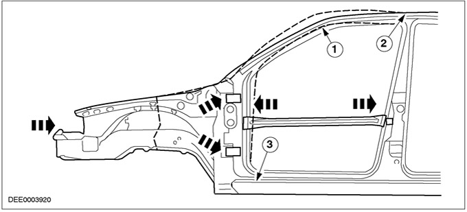
| Pos. | Spare Part No | Name |
| 1 | - | Warp zone - roof beam |
| 2 | - | Warp zone - roof |
| 3 | - | Warp zone - door sill |
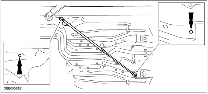
Bottom measurement
Measurements using a compass
- The compass is a very useful device for checking the underside of a car (under the bottom). It can be used to determine dimensional deviations in length and width (but not high) through comparative measurements and diagonal measurements. For this purpose, the reference points of the bodywork are always selected from the list of body frame dimensions.
Symmetry measurements using a compass
Body measurements
Measurement options
- Comparative measurements can also be made on the outside of the body. Depending on the damage, comparative and diagonal measurements can be made using a compass, telescopic rod, tape measure or ruler.
NOTE: When checking for resizing on both sides, select the same anchor points (e.g. holes, edges, collars, etc.).
- All important exterior dimensions of the body are listed in the description of body repairs for specific models.
Measurements using a measuring / straightening stand.
- A measuring/straightening stand is required to make accurate body floor measurements. Measuring systems are categorized according to how they work:
- Mechanical measuring system
- Optical measuring system
Fast and accurate measurement results can be obtained using computerized measurement systems.
A minimum of three undamaged measuring points located on the floor are required to determine length, width and height dimensions.
In some cases, this may mean creating accessible measurement points. All of these measurement systems can be used to perform body measurements, provided the appropriate equipment is available.
Measuring fixture for body measurements
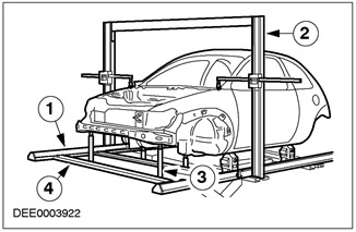
| Pos. | Spare Part No | Name |
| 1 | - | Main frame |
| 2 | - | measuring ruler |
| 3 | - | Telescopic measuring rod with measuring probe |
| 4 | - | Measuring bridge |
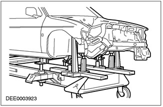
Alignment stand
Repair planning
Before starting repairs, the following decisions must be made:
- Does the car need to be leveled or can it be straightened in another way?
- Does the floor need measurements?
- Do units like the engine or axles need to be removed?
NOTE: It is preferable to repair body parts rather than replace them as this will avoid damage to the entire shell of the body. What body parts need to be replaced?
- Which body parts can be repaired?
Getting spare parts
The availability of spare parts often determines how easily a body repair can be completed. The following procedure is recommended:
- Get all vehicle details including type, vehicle identification number, trim code, engine identification letters, original registration data, and more.
- Identify all metal parts that need to be replaced.
- Identify all connected items that need to be replaced, including small items like rivets, clips, etc.
- After receiving all replacement parts, test them on the vehicle to make sure they are correct and complete.
Repair with editing
Straightening repairs are often required to restore the original body shape after a collision. This can be done using:
- Alignment stands
- Universal stand for straightening and measuring
- welding stand
To ensure that repairs are carried out professionally and that all dimensions are correct after repairs are made, the following points should be considered.
Structure:
- The repair sequence depends on the individual repair plan (accounting for any necessary dismantling work).
- Clean up connection areas.
- Secure the vehicle on an appropriate stand in such a way that no damage occurs to it.
- Support the units to relieve stress from the body.
- Stop at at least three measurement/reference points that are intact and as far apart as possible (for basic adjustment).
- Check the dimensions of the measurement/reference points.
Edit:
NOTE: Constantly check the dimensions and clearances during the dressing process.
- Body dressing is always done in the opposite direction to the impact. Always make adjustments with the body fully assembled (do not pre-cut any elements). Carry out editing in several stages. This prevents the risk of overstretching or tearing of welded joints. Each time you reshape while drawing, tap with an aluminum mallet to relieve stress (in areas of specified places of deformation, dents, welded joints, etc.)
Specific Features:
- High-strength low-alloy steel has a greater tendency to retain its deformed shape.
- If necessary, open the doors or hood when making adjustments.
- Never apply heat when dressing.
- Follow the instructions given in the section «Protective Equipment/Repair Safety».
Cutting body parts
Depending on which elements are connected, different tools are suitable for cutting/separating body parts.
NOTE: All other items such as interior fittings, window glass, etc. must be protected from projectile sparks.
NOTE: Be sure to set the milling depth correctly to prevent loosening of the remaining flange.
Milling of spot welds
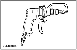
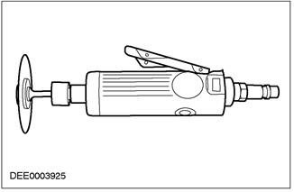
Face grinding wheel
NOTE: Use protective clothing. Protect any vulnerable body part or glass areas from projectile sparks. Remove explosive materials from nearby nearby areas.
- Any spot welds that are not available for milling (diameter > 8 mm) must be milled using a face (pivotal) abrasive circle. The same applies to spot and plain MIG welds.
End (pivotal) abrasive wheel
Cutting separation
NOTE: Below («subject») metal elements, wiring harnesses, hoses, etc. must not be damaged - if necessary, remove them beforehand.
- Bodywork saws are particularly versatile and are therefore well suited for separating body parts by cutting off.
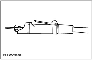
Short stroke saw
- Body parts are usually separated using a short stroke saw. It proves to be very flexible even in areas where access is very limited.
Short stroke saw
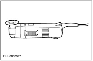
Reciprocating Saw
- In addition to the short stroke saw, a reciprocating saw can also be used. Using it, you can make narrow and straight cuts to the exact depth.
- The service life of the blade can be significantly increased by cooling the blade with oil. All chips generated during sawing should always be removed from the cavities (using suction), to prevent the risk of corrosion.
- If there are any solder joints on the element to be cut, use a welding torch to evenly heat the element until the solder is melted. Then separate «old» element.
Reciprocating Saw
Performing repairs
Complete replacement
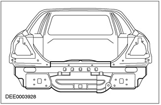
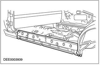
- With a complete replacement, the entire damaged «old» the element is separated at the places of its original connections and then a new element is installed in its entirety. The following figure shows the replacement of the rear panel with a new one (Mondeo).
Replacing the back panel with a new one (Mondeo)
Sectional replacement
- In many cases, it makes technical and economic sense to perform a sectional replacement. The two main considerations are, firstly, maintaining the complete original bodywork, and secondly, keeping repair costs to a minimum.
- There are three different ways of sectional replacement:
Butt joints
- The new element and the old element are connected by a continuous MIG weld.
- Butt joints are commonly used when sectional replacement of elements of the power set and racks or when separating a element with a short cut.
Butt joint
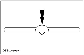
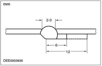
Edge bending
NOTE: Although the folded edge is 12mm, only 10mm should be given as allowance for the new element. This automatically creates a predetermined welding gap between the edge «old» panel and the edge of the new panel. Before installing a new element, the created edge is reduced to 6 mm for reasons of corrosion protection.
- Edge bending is mainly done on «old» element that is still connected. «Old» the element and the new element are connected with an interrupted seam.
Edge bending
Metal backing strip
- Metal backing strip (approx. 30 mm wide) from the abandoned «old» element or a new element is spot welded to the back of the joint.
NOTE: Bent edge or metal backing strips are usually used for longer cuts.
NOTE: For sectional replacements, cuts for separation should always be kept as short as possible. In the model-specific chapters, only cutting lines are shown.
- Do not make any cuts near the reinforcement or in zones of predetermined deformation.
NOTE: Do not start cutting «old» element until a new element is delivered (repair sections can vary in size).
- Special repair sections are available for sectional repairs and are listed separately in the Microfiche for spare parts.
Metal backing strip
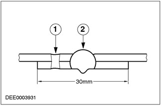
| Pos. | Spare Part No | Name |
| 1 | - | Contact spot welding |
| 2 | - | Intermittent MIG weld |
Panel repair sections - Ford Ka
Sectional replacement - spar, Ford Puma
Prepare «old» elements that remain on the vehicle / new elements.
- Restore the original shape of the adjacent surface of any dented body parts that should remain on the vehicle using a hammer and mating tool (ensures shape conformity «old» element and new element). Remove, using an angle grinder, spot or other welds.
- Cut the new elements according to the shape.
- If necessary, punch or drill holes for spot welding.
NOTE: Do not use welding torch to remove paint residue (heat can cause the metal to warp).
- On both sides, clean all connecting flanges to bare metal. Do not use an angle grinder for this purpose (this can weaken the metal and damage the zinc layer). Appropriate tools: rotary wire brush, belt sander or plastic disc.
- Excluding solder joints, liberally apply welding primer to all welding flanges.
- The primer should be well mixed before use.
NOTE: When using aerosols, be careful not to contaminate adjacent areas when spraying the aerosol.
NOTE: For more information, see Section 501-25B «Body Repair - Corrosion Protection».
Install a new item.
Make sure that the new element exactly corresponds to the prescribed dimensions. Related equipment:
- Alignment stand
- Universal measuring system
- assembly stand
- Ruler or tape measure
- Compass
- Frame dimensions can be found in the repair manuals for specific models.
NOTE: At this stage, any attached body parts that require precision alignment and installation, such as bumpers, seals, headlights, taillights, and lock assemblies, should be installed. If this is not done carefully, it can lead to water leaks, wind noise intrusion and a significant amount of follow-up work.
Make sure the edges are aligned with adjacent elements and check for correct gaps (compare left and right sides). Make sure the shape of the car is maintained.
Pinning a new element
NOTE: The need for subsequent work can be greatly reduced if alignment and tack welding are done with due care.
Depending on availability, the following fixing methods are available:
- pliers (set)
- Screw terminal (set)
- Self-tapping screws
- Potholders
Use a center punch or screwdriver to ensure that the edges of the profiles line up when replacing in sections. The edge is then tack welded to ensure it is in the correct position.
Alignment and tack welding
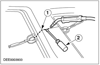
| Pos. | Spare Part No | Name |
| 1 | - | Potholders |
| 2 | - | Using a screwdriver to align the position |
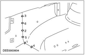
Longer joints are usually tack welded to prevent warping of the panel. It is important to weld tacks in the correct sequence (see diagram).
Weld the new element following the instructions in the repair manual. Read and take note of the comments in Chap. «Repairs with welding and soldering».
Correct tack welding sequence
Subsequent repairs / corrosion protection
This section is mainly devoted to the following work:
- Cleaning of welds and, if necessary, filling them with lead.
- Bare metal primer.
- Sealing of welds.
- Applying a protective coating to the bottom.
- Installation of damping lining.
- Filling cavities with foam.
NOTE: Refer to Section 501-25A / 501-25B / 501-25C / 501-25D / 501-25E / 501-25F / 501-25G for more information. «Body Repair - Corrosion Protection»
- Mastic for cavities (when staining).
Tapping (straightening) panels
Types of steel used in the manufacture of the body
- Car bodies are made of thin sheet steel with a thickness ranging from 0.5 to 2.75 mm. There are two main types:
- Body panels made of quality stamped steel
- High strength low alloy steel
- Body panels made of quality stamped steel:
- These body panels are softer and more easily stamped. They stretch extremely well and are therefore not susceptible to unwanted cracking.
- High strength low alloy steel:
- High-strength low-alloy steel is much more resistant to stamping or other processing than, for example, ST14 steel. It also has a higher tensile strength.
Basic principles of tapping panels
- Before performing any sectional or full body panel replacements, always check carefully to see if a damaged panel can (And) be corrected by tapping.
- tapping (straightening) panels are usually the easiest and most economical method of repairing a damaged panel.
Examples of the application of various panel tapping technologies:
- Aluminum hammer and wooden hammer
- Benefit: Low chance of panel overstretch.
- Used to repair small dents in panels that can be accessed from both sides.
- These two panel tapping tools are commonly used for «final repairs».
«Thin» straightening with an aluminum hammer and a universal backing die
Hammer with movable striker
- If the damaged panel is only accessible from the outside, use a moving hammer to restore the panel's shape. The discs or studs needed to mount a moving hammer are welded to the bare metal surface. Dents in the panel can be corrected using the controlled action of a hammer with a moving striker.
Heat treatment of panels
- It is usually inevitable that, as a result of mechanical deformation, some parts of the body panels show the presence of excess material. If there are any areas of excess material, this causes limited buckling due to differences in material tension. These local buckling zones can be stabilized by heat treatment.
NOTE: This rule does not apply to high strength low alloy steel.
Rule: Straightening panels by heat treatment reduces the amount of excess material to a greater extent than initial stretching.
Various heat treatment methods
NOTE: Depending on the amount of excess material, different heat treatment methods are used.
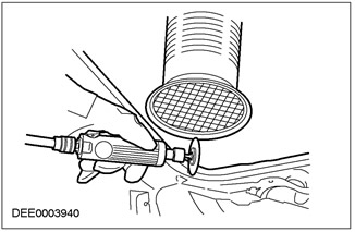
- Flame dressing
- If excess material is observed in a significant area, a welding torch is used (burner size 0.5 - 1.0 mm). Use a weak flame.
- The surface of the metal is briefly heated in patches and then immediately cooled with a damp sponge.
- Requirement: Ability to properly handle the welding torch and knowledge of steel annealing colors.
- Advantage: No damage to the metal surface.
- Dressing with a flame in combination with a hammer and counter tool
NOTE: Dressing efficiency is increased by faster heating and cooling.
- If the excess material is concentrated, then the dressing efficiency can be increased by carefully using an aluminum or wooden mallet after heating.
- Requirement: Ability to recognize the stress state of the material by observing the surface to be dressed.
- Dressing with carbon electrode
- If the panel areas are only accessible from one side, or if the panel is only slightly buckled, carbon straightening is the preferred straightening method.
- Requirement: Bare metal surface.
- Disadvantage: The presence of scratches and hardening of the surface.
- Dressing with copper electrode
- Small, sharp dents that face outwards can be repaired using a copper electrode.
- Dressing with a flame and shaped files for bodywork
NOTE: When used correctly, this method can be used without removing all attachments (roof sheathing, wiring harnesses, etc.).
- Small dents (with only slight stretch): When processing the edges of the dent in a spiral inward direction, the dent is heated with an oxy-acetylene torch (burner size 1 - 2 mm, excess gas flame) up to a temperature of approximately 250°C.
- Fast work with a body file removes heat from the boundary zone and so on until the dent is straightened. It is preferable to alternate work with two files. This increases the amount of heat that can be removed.
Filling panels with lead
Filling panels with lead is the best repair method for straightening joints in sectional repairs or to eliminate small areas of unevenness on the surface of the panel. Advantages:
- Excellent adhesion to bare metal surfaces.
- Very good forming properties.
- Good properties for reshaping.
- permanent form.
- Thermal expansion is the same as that of steel.
NOTE: Tin Alloy: PB 25% / 75%. Use suction. Breathing equipment.
Process: Hammer the applied lead weight before final finishing to remove air bubbles.
Repair with welding and soldering
Precautionary measures
NOTE: Refer to the notes given in Chap. «Protective Equipment/Work Safety».
- Disconnect the battery ground wire and cover the terminal to protect the vehicle's electronic modules (ABS, airbags, etc.).
- Do not allow electronic components or lines to come into contact with «weight» or welding electrode.
- Remove the battery before welding near it.
- Be extremely careful when welding near a fuel tank or other items that contain fuel. If the filler neck or fuel line must be separated to gain access for welding, the fuel tank must be emptied and removed.
- Never weld or solder any type on the components of a charged air conditioning system. The same is true if there is a risk of heating up the air conditioning system.
- Connect the earth connection of the electric welding equipment directly to the element to be welded. Make sure there are no electrical insulators between the ground connection and the welding site.
- Neighboring elements of the vehicle and adjacent vehicles should be protected from sparks scattered during welding and exposure to heat.
Contact spot welding
90% of welds in the manufacture of a car are carried out by resistance spot welding. As a general rule, repairs should use the same joining technique that is used in the manufacture of the vehicle. The number and diameter of welding points during repair must be the same as during the manufacture of the car. An alternative connection technology may only be used in exceptional cases.
Setting up equipment and welding parameters
Equipment:
- Follow the hardware manufacturer's instructions to set up the hardware.
- Choose the right electrode holders (as short as possible).
- Accurately align the position of the electrode holders and tips.
- The tips of the electrodes must be convex (roughly shape with a file, fine-tune the shape with a grinder).
Body:
- Make sure that the flanges to be joined are perfectly aligned with each other.
- Prepare a clean metal surface at the joint (inside and outside).
Notes on the methodology / technology:
- Make a test weld on a piece of material covered with welding paste.
- If any metal elements are placed between the electrode holders, there will be a loss of induction and, consequently, power (current adjustment
- For high strength low alloy steel, power adjustment is required.
- Re-welding over old welds often leads to poor weld quality.
- Hold the electrode tips at an angle to the contact surface as close to 90°as possible.
- Maintain pressure on the electrodes for a short time after welding is complete.
NOTE: Cool the electrodes in water after approximately 10 spot welds to ensure proper welding quality (no need for cooled electrodes).
- Electrodes work best if they are convex. Regularly clean the contact surface of the electrodes.
Resistance spot welding of panels when the total thickness is 3 mm or more
To repair all modern Ford vehicles, resistance spot welding equipment must be able to reliably weld galvanized and high strength steel panels with three or more layers, up to a total thickness of 5 mm. If these requirements are not met, puddling should be used for safety reasons. Electrical specifications (current, resistance, heat) resistance spot welding equipment differ depending on the type of equipment. Therefore, with regard to the actual characteristics of the welding process, it is important to follow the equipment manufacturer's instructions.
MIG/MAG welding
Setting up equipment and welding parameters
Any joints welded using MIG/MAG technology during the manufacture of the vehicle must be welded using the same technology during the repair process. Also during the repair process, some spot welds must be replaced with puddling welds.
If access is difficult or there is no welding equipment for spot welding of adequate power (see above) for total panel thickness of 3mm or more, sometimes resistance spot welding should be replaced by puddling welding during repair. In this case, an increase in time is required and, accordingly, the stricter requirements for corrosion protection should be taken into account.
Repair with welding can only be carried out correctly if the equipment is set up correctly and all welding parameters are correct.
Equipment:
- Set up the equipment in accordance with the manufacturer's instructions.
- The hoses must not be twisted.
- The core must be free from abrasive particles.
- Gas nozzles must be free from slag and scale.
- Pay attention to the quality of the welding electrode and gas consumption.
body type:
- Check the quality of the surfaces to be joined.
- Prepare a bare metal surface at the joint.
- Ensure clearances are maintained correctly (root formation).
Notes on the methodology / technology:
NOTE: The increased heat input of MIG welding destroys the weld primer/zinc over a much larger area than resistance spot welding, resulting in much more attention to subsequent anti-corrosion coating applications.
NOTE: To ensure that the weld is not just a surface joint, a test weld should always be made.
- Connect the earth cable near the welding site (make sure the contact quality is good).
- When performing puddling welding, start welding at the bottom panel to ensure adequate penetration.
Puddling welding
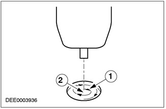
| Pos. | Spare Part No | Name |
| 1 | - | Welding direction: move in a circle from the inside to the outside |
| 2 | - | Starting point of welding: center of the hole on the bottom panel |
Solder connections
Never replace factory solder joints with any other type of joint.
NOTE: To prevent the risk of corrosion, remove all traces of flux.
Soldered joints require especially careful preparation. It is extremely important that the surfaces to be joined are precisely aligned and that a clean, bare metal surface is prepared at the joint.
Adhesive joints
Bonding technology is increasingly used in the automotive industry. Some areas of the body are affected more and more. All adhesive joints during the repair process must be restored.
Operating Instructions and Safety Rules
- When using adhesives or sealants, always follow the manufacturer's instructions.
NOTE: Follow the manufacturer's safety instructions.
- Adhesives are chemicals and therefore meet specific safety regulations.
Bonded flanges
- Hood, tailgate and door flanges are bonded during vehicle manufacture and during repairs on many Ford models.
- These connections are mainly intended for sealing purposes (anti-corrosion), and not for strength.
Connections requiring strength
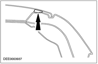
- Adhesive joints that require strength are used for bonding strength, sealing purposes, and corrosion protection purposes (e.g. 1991 Escort/Orion in the rear roof area, near the transition to the pillar «WITH»).
- The glue used for this purpose is 2K epoxy.
Adhesive bonding of the outer skin of the roof (Escort 1991)
Bonded glazing
- On almost all models, the windshield is glued directly into the window frame on the body. In addition, in most versions of the models, the glass of the side and rear windows is glued.
- Window panes are glued primarily for reasons of ensuring the strength of the adhesive bond. The glued glazing gives the body additional torsional rigidity.
Adhesive bonding on windows with glued glass
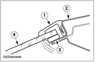
| Pos. | Spare Part No | Name |
| 1 | - | Rubber strip |
| 2 | - | window frame |
| 3 | - | Glue |
| 4 | - | window glass |
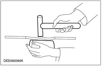
Removal and installation of windows with glued glass
Safety regulations
To prevent injury, the following safety precautions should always be observed:
- Use protective gloves.
- Use safety goggles.
Preparation
- Before cutting a window with glued glass, loosen and remove all connected parts that are in the cutting area that are at risk, such as trim panels and decorative strips, as well as all electrical connections.
- Close all painted areas that are located next to the window.
- Trim off any excess glue, as this makes it easier to cut the glass.
- Secure the vertically positioned windows to prevent them from falling out.
window glass cutting
- Cut along the glue bead in easily accessible places using a cutting tool.
- Gently guide the cutting tool around the perimeter of the window, cutting through the bead of adhesive.
- Avoid touching the window frame and body flange.
- Use special «suction pads», to remove the glass from the window opening.
General preparations for the gluing procedure
- Follow the manufacturer's instructions.
- Trim the remaining adhesive bead on the metal flange to a residual height of approx. 1 mm. Do not touch or clean the cutting surface afterwards.
- Carefully repair any damage to the paintwork (apply primer and top coat).
- Replace window stops if necessary.
Window glass bonding
- Apply an even bead of adhesive to the window or body flange.
- Insert the glass into the window opening and center it (2 technicians required).
- Check gaps.
NOTE: Open windows and doors while the window is left to dry, and do not move the vehicle (slamming doors creates excess pressure that can cause the window to loosen).
Use adhesive tape to prevent the glass from falling out.
Final operations:
- Connect all electrical connections and check the correct operation of the elements.
- Install the connected elements and check the accuracy and reliability of fastening.
- Perform a visual inspection to ensure that gaps and connections are even.
- Completely clean the window glass.
Special body repairs
flip top
- The convertible body is significantly different from «sedan». These differences apply not only to its appearance and functionality. To achieve the required stability, it is necessary to strengthen the structure.
- The design of a closed body with a shell is not possible, because there are no roof beams. Therefore, in order to ensure sufficient stability (especially with regard to torsional rigidity) The convertible top uses a different method. This is achieved through structural changes to existing body elements «sedan» and installation of additional reinforcing elements.
Reinforcement of the door sill area
NOTE: If a damaged vehicle is placed on a straightening stand with all of its components remaining in place, the body needs support to take some of the load off.
When performing body repairs, the following design features should be noted:
- Large material thickness, e.g. in the area of the door sill.
- Different behavior during editing.
- Particularly high installation accuracy is required; e.g. for the attachment points of the convertible top.
- The installation of the drop roof and adjacent bodywork should be checked during and after repair to ensure that it is water tight, wind noise proof and properly closed.
- Off-road vehicles («SUVs»)
NOTE: If the body is bolted to the chassis, all bolted connections between the body and chassis should be checked for damage during straightening.
NOTE: If the damage to the body and chassis is more severe, the body should be removed from the chassis. Both elements are then edited separately.
- «SUVs» have a load-bearing chassis to which the body is bolted.
- If during the repair process any editing becomes necessary, then special universal sets of supports or straightening stands are used.
Protective equipment and work safety
- Various safety and legal requirements must be observed when carrying out repairs. Comply with all health and safety regulations.
Welding Precautions
To prevent the risk of injury, the following precautions should be observed:
- Welder's mask (face protection)
- Screen
- Protective gloves
- Safety boots
- Welding fume extractor
Welding should always be done in a well ventilated area. A fire extinguisher must always be within reach.
General Safety Precautions When Performing Body Repairs
Sucking
- Sealant, underbody protection, etc. should not be burned using an open flame. This results in the release of toxic gases. When PVC is burned, for example, gases containing hydrochloric acid are released. For this reason, when grinding, welding or soldering, always use the correct suction.
- Always ensure good ventilation when working with materials that contain solvents, use respiratory protection and suction equipment.
- Ear protection should always be worn when cutting, grinding or straightening metal, as noise level can reach or even exceed 85 - 90 dB (A).
- Be careful not to look directly into any laser measurement systems, such as those used for floor measurements.
- When removing elements from a car mounted on a lift, watch for changes in the position of its center of gravity. When placing the vehicle on a lift for the first time, please note that it may be necessary to secure it to prevent it from tipping over.
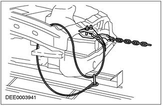
- During straightening, chains and chain clamps should be secured using safety ropes.
Safety wire
Visitor comments