


Removal
Remove the gearbox, see p. 89.
To prevent the flywheel from turning when the bolts are loosened, secure it to the ring gear using a screwdriver and pin.
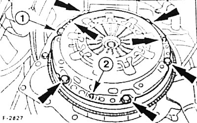
Loosen the bolts (outer arrows and "1") securing the pressure plate to the flywheel in a crosswise manner by 1-1.5 turns to reduce the tension on the pressure plate.
Caution: If the bolts are completely removed at once, the diaphragm spring may be damaged.
After this, unscrew the mounting bolts completely.
Remove the pressure and driven clutch discs.
Attention: When removing the discs, do not drop them, otherwise after assembly difficulties may arise associated with clutch jerking and disc separation.
Wipe the flywheel with a rag soaked in gasoline.
Examination
If the old pressure or driven clutch discs are installed, they should be checked before installation.
Replace clutch discs with traces of oil and grease, as well as with mechanical damage.
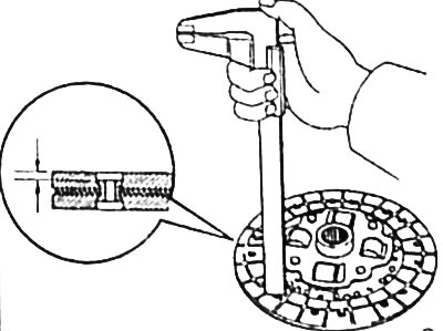
Check the thickness of the clutch slave disk linings using a caliper. The distance to the rivet heads should be at least 0.3 mm, otherwise replace the slave disk. If cracks are found on the linings, the disk should also be replaced.
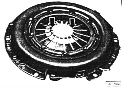
Check the pressure plate. Examine the diaphragm spring for signs of wear at the point of contact with the clutch release bearing. Wear of the ends of the diaphragm spring "arrow" to a depth of up to 0.3 mm is allowed.
Check the spring connections between the pressure plate and the cover for cracks and the strength of the riveted connections. Replace the coupling with damaged or loose rivets.
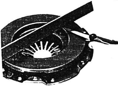
Check the contact surface of the pressure plate for cracks, burns and wear. Pressure plates with inward deflections of up to 0.3 mm can be reinstalled. The check is performed with a metal ruler and feeler gauge.
Check the flywheel for cracks from burns and unevenness.
Sand the pressure plate with very fine sandpaper.
At the service station, the driven clutch disc can be checked for runout. Lateral runout should not exceed 0.25 mm.
Attention: This check is required in the case where the previous driven disk is installed and the clutch was previously disengaged incorrectly.
Check the clutch release bearing in the gearbox housing. There should be no visible signs of pressure on the bearing. Turn the bearing by hand. It should rotate easily. A bearing that makes noise when the clutch pedal is pressed should be replaced, see p. 86.
Installation
Caution: Before installing a new clutch, remove the protective varnish from the friction surfaces of the pressure plate with solvent and, if necessary, wipe the flywheel.
Apply a thin layer of special grease (Microlube GL-261) to the splined connection of the drive shaft and the guide sleeve. Lubricate all surfaces of the splines.
Caution: Do not apply too much grease, as excess grease will be thrown onto the friction surfaces and will cause the clutch to malfunction. Using other grease may also cause the clutch to malfunction.
Check the tightness of the fit of the centering pins for the clutch housing on the flywheel.
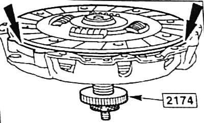
Adjust the drive disk visually to the center of the pressure plate. However, it is best to use a suitable pin for this, for example. HAZET 2174 or an old drive shaft of the gearbox. At the service station, a special tool FORD 21-044A is used for this. If the driven disk is not located in the center, then the drive shaft of the gearbox cannot be inserted.
Place the pressure plate together with the centered driven disk on the flywheel. The flat side of the driven disk with the inscription Flywheel Side / Schwungradseite must face the flywheel (towards the engine). Observe the position of the centering pins. See Figure F-2B27 (inner arrows and "2").
Insert and tighten the pressure plate mounting bolts by hand.
Tighten the pressure plate mounting bolts in succession in a crisscross pattern by 1-1½ turns until the plate is securely tightened.
Caution: Do not tilt the pressure plate when tightening the bolts. The tightening torque for the pressure plate mounting bolts is 30 Nm.
Remove the centering pin.
Install the gearbox, see p. 90.