Fuel Injection Harness Connectors
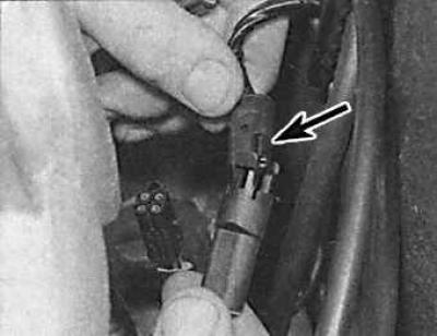
The wiring harness connector is indicated by an arrow.
Places for applying sealant to mating surfaces
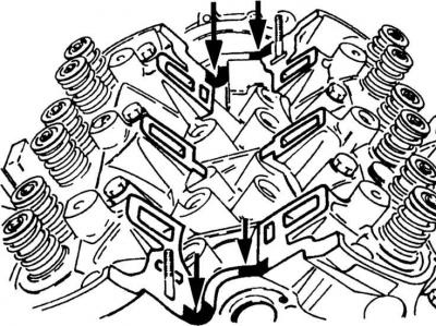
Places of application of sealant are indicated by arrows.
Removal from the manifold of the fuel line and injection valves
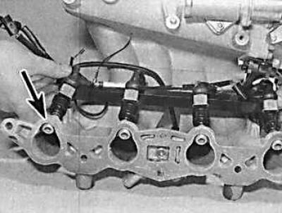
The injection valve is indicated by an arrow.
OHC engines
1. Remove ground wire from battery.
2. Drain coolant.
3. Disconnect the vacuum tubes from the manifold. The number of tubes depends on the model and equipment.
4. Remove the fuel injector harness connectors at the end of the line closest to the baffle.
5. Disconnect the oil pressure warning light sensor wire under the manifold.
6. Loosen the clamps and remove the line, air flow meter and pipeline from the manifold.
7. Remove the distributor cap and disconnect the high voltage wires.
8. Unscrew the two nuts and remove the support from the manifold to the right side of the cylinder head.
9. Unscrew the four bolts and remove the support that connects the manifold base to the left side of the block.
10. Unscrew the accelerator cable bracket and move it to the side.
11. Disconnect the fuel supply pipe from the fuel bracket and the return pipe from the fuel pressure regulator.
12. Disconnect the coolant hose from the manifold.
13. Unscrew the six nuts and bolts securing the collector (indicated by arrows) and take it off. A ground wire can be connected to one of the studs with an additional nut.
14. Carefully remove manifold with fittings from cylinder head. If the distributor interferes with removal, unscrew the front manifold stud or remove the distributor.
15. Remove the gasket from the cylinder head.
16. Installation is made in sequence, return to removal. Apply sealant to mating surfaces.
DOHC engines
1. Remove ground wire from battery.
2. Drain coolant.
3. Disconnect the coolant hoses from the thermostat housing and intake manifold.
4. Disconnect the air intake pipe from the front of the intake manifold.
5. Disconnect the crankcase ventilation hoses and vacuum hoses from the intake manifold.
6. Disconnect the accelerator cable.
7. Remove the high-voltage wires from the spark plugs and move them to the side.
8. Disconnect the wires from the radiator fan switch, engine coolant temperature sensor, and temperature sensor.
9. Remove the throttle position sensor connector.
10. Remove fuel injectors.
11. Unscrew the 10 bolts and 2 nuts securing the manifold to the cylinder head and carefully remove the intake manifold. Remove gasket.
12. Remove the 2 plastic spark plug gaskets from the socket in the cylinder head.
13. Installation is made in sequence, return to removal. Pour coolant into the cooling system and check idle speed and CO content.
V6 engines
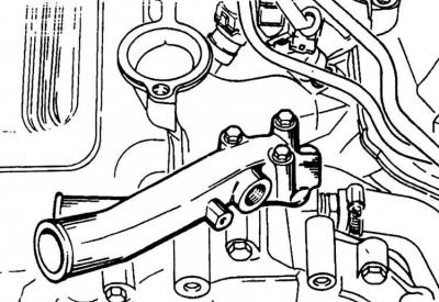
Outlet connection of the cooling system on the inlet pipeline of the V6 engine
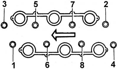
The procedure for tightening the intake manifold mounting bolts V6 engines
1. Remove ground wire from battery.
2. Drain coolant.
3. Remove the throttle lever cover.
4. Loosen the clamps and move the air flow meter-collector to the side of the line.
5. Remove the crankcase breather hose.
6. Remove the upper radiator hose and heater hose from the outlet on the front of the piping.
7. Disconnect the connectors from the idle speed valve, temperature sensor, coolant temperature sensor, and throttle position sensor. Disconnect the fuel injector harness.
8. Disconnect the accelerator cable from the lever. On automatic transmission models, also disconnect the kick-down cable or connector.
9. Disconnect the fuel supply and return pipes.
10. Remove high voltage wires and ignition distributor.
11. Unscrew the eight bolts and remove the overpressure chamber.
12. Unscrew the seven bolts and remove the cylinder head covers.
13. Disconnect the water pump bypass hose from the intake manifold.
14. Unscrew the eight bolts and remove the intake manifold.
15. Remove intake manifold with pressure regulator, fuel bracket and throttle body shroud.
16. Installation is made in sequence, return to removal. Apply sealant to mating surfaces.
Visitor comments