Anti-lock braking system
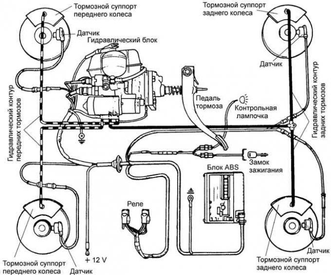
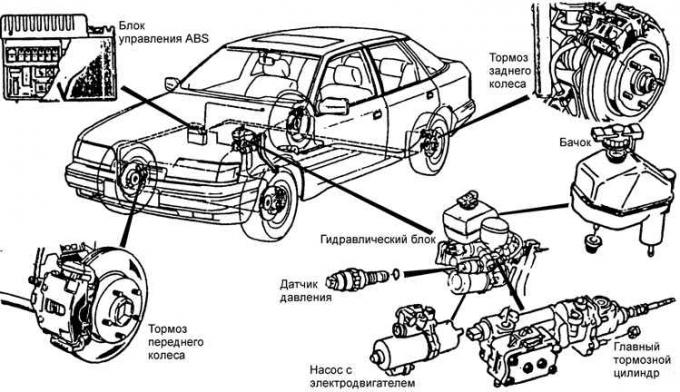
Location of anti-lock braking system components
Operating principle
Braking efficiency is greatest when the tire's grip on the road surface is at its maximum. During braking, the tire slides along the surface and the wheel's circumferential speed becomes less than the vehicle's speed.
Slip is minimal (0%) when the wheel rolls freely and maximal (100%) when the wheel is locked. Maximum braking efficiency is achieved when slip is 15%. This value also helps maintain vehicle stability and control.
The role of the anti-lock braking system is to limit the pressure generated in the hydraulic brake system so that the amount of slip is kept near the optimum value (15%). The action of this system must be immediate and separate for each wheel. The system must respond immediately to every change in the surface (adhesion coefficient) and the load on the vehicle.
Design
The Teves anti-lock braking system (ABS) contains four wheel speed sensors, a hydraulic control unit and an electronic control unit.
Four sensors (at each wheel of the vehicle) transmit signals to the electronic control unit informing about the rotation speed of each wheel of the vehicle.
The electronic control unit, located on the right side under the front panel, based on the information received about the uneven speed of rotation of individual wheels (or about their blocking) transmits a command to the hydraulic control unit to reduce the braking force (pressure supplied to the brake caliper) of the wheel that has begun to experience excessive slip. The electronic control unit also performs an auto-diagnostic function, warning the driver by lighting a control lamp about the registration of a malfunction of electrical circuits or elements of the anti-lock system. If the ABS system is faulty, the brakes are nevertheless in good condition and function as if this system is not in the car. The only control lamp warns the driver that the ABS system is not correcting his errors.
The hydraulic control unit contains a tandem master cylinder that controls the front brakes and a hydraulic auxiliary device that controls the rear brakes. The hydraulic auxiliary device contains six electromagnetic valves controlled by an electronic control device that regulates the brake pressure of individual wheels and, therefore, the braking force. Three inlet electromagnetic valves remain open during normal braking (without slipping), and three outlet valves remain closed. They are located in the circuits of the right front brake, left front brake and rear brakes.
Functioning
When one of the four speed sensors signals that the corresponding wheel is locked, the electronic control unit immediately issues a closing signal to the corresponding inlet solenoid valve, which immediately shuts off the supply of brake fluid through the brake pipe to the brake of this wheel - the braking force remains constant. If the slip still continues, the outlet valve opens and the pressure in the hydraulic system of this brake decreases - the wheel is not braked (the excess brake fluid returns to the reservoir). As soon as the wheel starts to rotate again, the inlet valve opens and the outlet valve closes immediately. The pressure in the circuit increases, and the wheel is braked again.
This cycle of braking and free rotation of the wheel occurs very quickly (several times per second) and continues until the car stops or until the brake pedal is released.
The anti-lock braking system (ABS) operates at speeds above 7 km/h.
[The text was obtained in its entirety from the specified website: FORDBOOK.RU]